
Foundation system for electrical utility structures

a technology for electrical utilities and foundation systems, applied in the direction of machine supports, other domestic objects, mechanical apparatus, etc., can solve the problems of affecting affecting the installation cost, and requiring significant time and labor, so as to minimize the impact on the chosen construction site, minimize labor, and minimize the effect of associated installation costs

Active Publication Date: 2014-03-25
MEYER UTILITY STRUCTURES LLC
View PDF50 Cites 4 Cited by
  • Summary
  • Abstract
  • Description
  • Claims
  • Application Information

AI Technical Summary

Benefits of technology

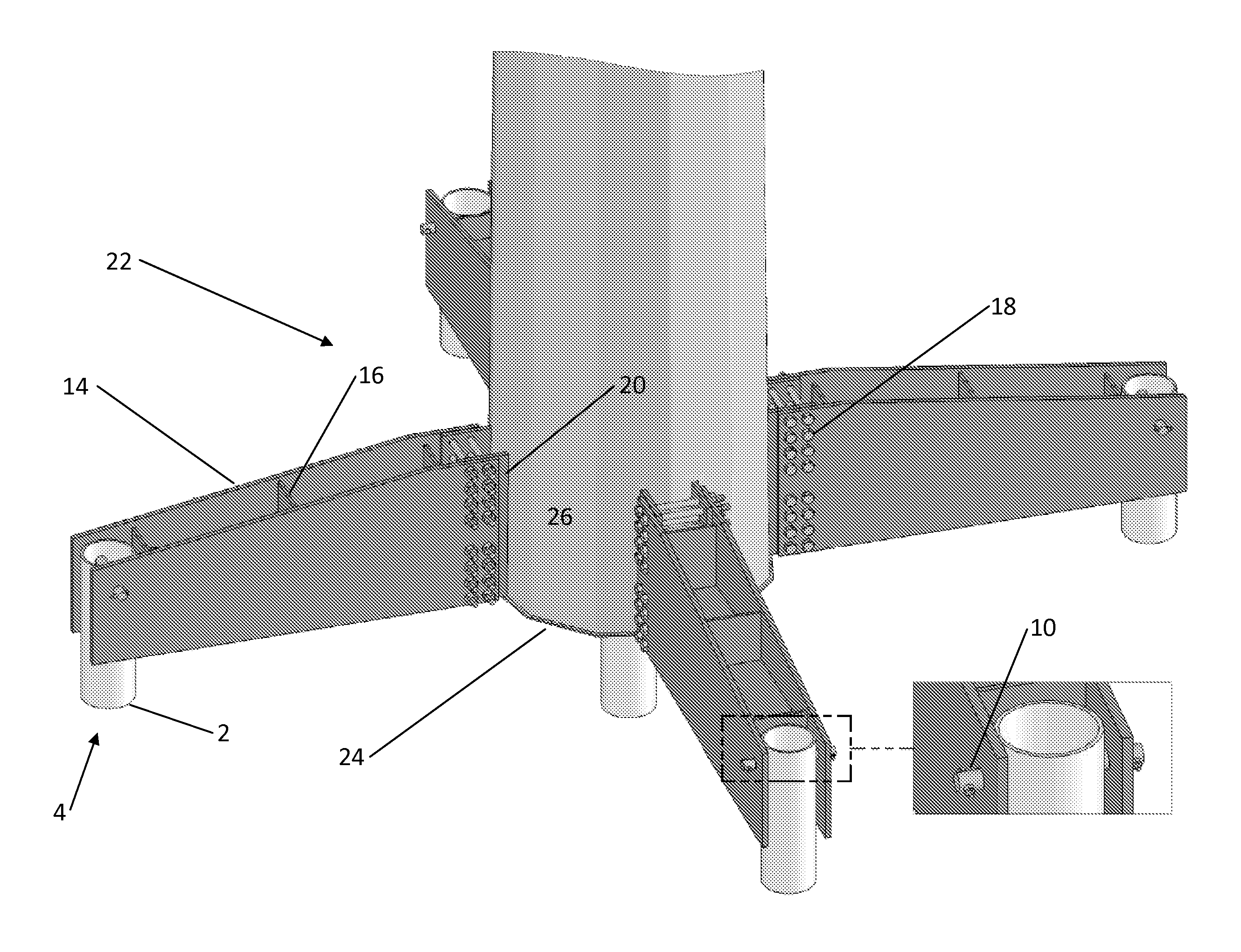
[0004]The present invention provides a foundation system for electrical utility structures which minimizes impact on the chosen construction site, minimizes labor and minimizes associated installation costs. The present invention includes a structure that has a base and which is supported at the base by multiple helical piers which are driven into the ground and indirectly attached to the structure base by arm members. The arm members attach to the helical piers at their distal ends by a pin connection or a bolted connection. The arm members may be either elongated plate arms with gussets or pipe spacers for stiffening support or arm members which have polygonal cross-sections. The arm members attach to the base of the structure either by slotted, perpendicularly intersecting thru-plates which protrude from the walls at the base of the structure or by doubler assemblies which are welded to the outer walls at the base of the structure. If doubler assemblies are used to connect the arms to the base of the structure, stiffening rings may also be used in conjunction with the doubler assemblies in order to provide lateral support and resistance to local buckling, punching shear or torsional forces. A pin connection or a bolted connection may be used to attach the arms to the base of the structure using either of the previously described methods.

Problems solved by technology

Both of these methods for installing electrical utility structures require significant amounts of time and labor, and they impact the chosen construction site.
Direct embedment and anchor bolt foundations require the use of heavy equipment which can lead to an adverse impact on the construction site and expensive installation costs.
Neither of these options is sufficient when a strict timeline must be met and minimal site disturbance is required.

Method used


Image

  • Foundation system for electrical utility structures
  • Foundation system for electrical utility structures
  • Foundation system for electrical utility structures

Examples


Embodiment Construction

)

[0021]The above and other features, aspects and advantages of the present invention will now be discussed in the following detailed description of preferred embodiments and appended claims, which are to be considered in conjunction with the accompanying drawings in which identical reference characters designate like elements throughout the views.

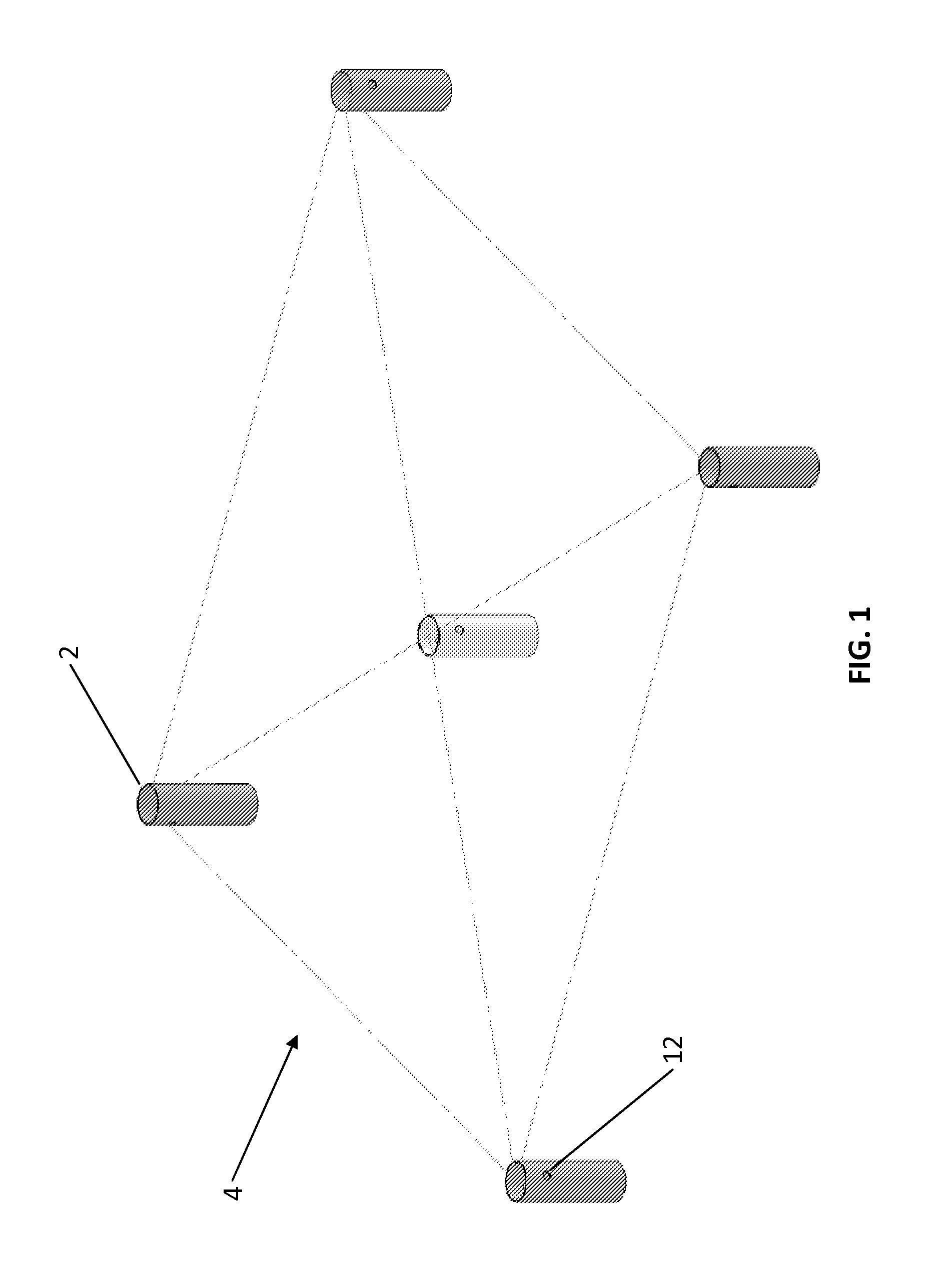
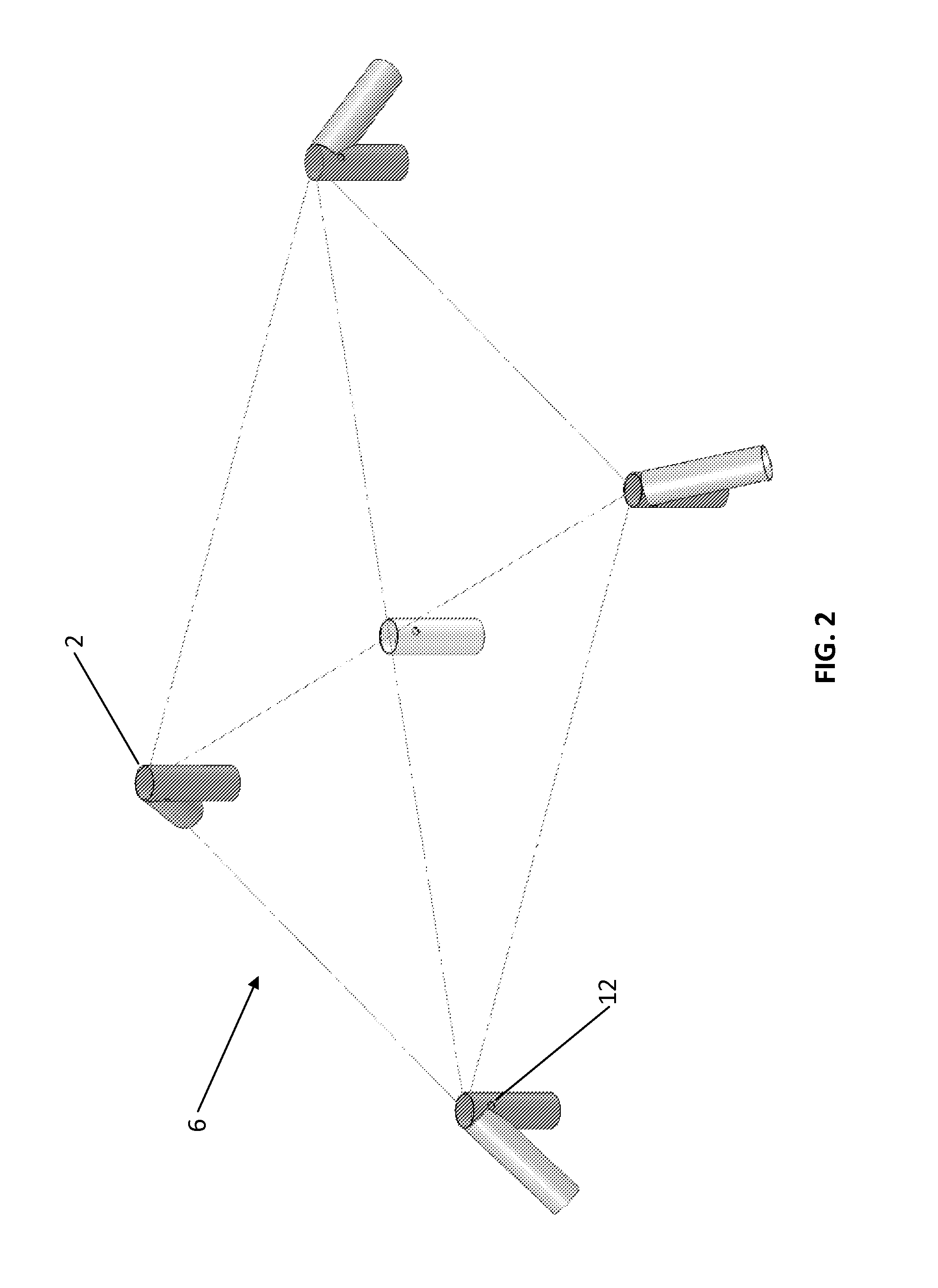
[0022]Shown in FIG. 1 is a front perspective view of a single helical pier system 4 of the present invention. FIG. 1 illustrates the embodiment of the helical piers 2 embedded in the ground as a square arrangement, with one helical pier 2 at each corner of the square and one helical pier 2 in the center of the square, which may or may not be required and which, if required, would be situated directly beneath an electrical utility structure that is being supported by the helical pier system. The embodiment of the single helical pier system 4 is not limited to a square arrangement, but may be any shape arrangement which is suitable for suppor...


PUM


Abstract

A foundation system for electrical utility structures is provided that minimizes impact on the chosen construction site, minimizes labor and minimizes associated installation costs. The foundation system comprises a structure to be supported at its base which has a plurality of arm members secured to the base and a plurality of helical piers or micropiles which are inserted into the ground and distally attached to the base of the structure by attaching to the arm members.

Description

CROSS-REFERENCE TO RELATED APPLICATION[0001]This application claims priority under 35 U.S.C. §119, based on U.S. Provisional Patent Application No. 61 / 605,517, filed Mar. 1, 2012, the disclosure of which is hereby incorporated by reference herein.FIELD OF THE INVENTION[0002]In general, the present invention relates to a foundation system for electrical utility structures. More particularly, the present invention relates to a structure to be supported at its base, a plate cap which is welded to the base of the structure in order to hermetically seal the structure from the elements to prevent corrosion of the interior of the structure, and multiple helical piers for insertion into the ground that are indirectly attached to the base of the structure by multiple arm members which are attached to the base of the structure and distally connect the helical piers to the base of the structure.BACKGROUND[0003]In the electrical utilities industry, options for installing electrical utility stru...

Claims


Application Information

Patent Timeline
Patent Type & Authority Patents(United States)
IPC IPC(8): E02D27/00
CPCY02E10/728E02D27/42
Inventor FAIRBAIRN, MARKJACKSON, AUBREYJACOBS, EDMOLINE, STEVEMUMM, THADPALMER, JIM
Owner MEYER UTILITY STRUCTURES LLC
Learn More