
Attachment stud for a variable vane assembly of a turbine compressor

a technology of variable vane assembly and attachment stud, which is applied in the direction of machines/engines, climate sustainability, fastening means, etc., can solve the problems of affecting the performance of the synchronizing ring, the synchronizing ring weight is typically not supported by the synchronizing ring, and the engagement used in conventional assemblies often produces excessive wear on the assembly components

Active Publication Date: 2014-03-11
GE INFRASTRUCTURE TECH INT LLC
View PDF46 Cites 30 Cited by
  • Summary
  • Abstract
  • Description
  • Claims
  • Application Information

AI Technical Summary

Benefits of technology

The solution significantly reduces wear on components, maintains the concentricity of the synchronizing ring, and distributes the ring's weight evenly, thereby improving the operational efficiency and longevity of the variable vane assembly.

Problems solved by technology

This sliding engagement generally produces excessive wear on the assembly components disposed at this sliding interface.
Moreover, the sliding engagement utilized in conventional assemblies often provides inadequate support for the synchronizing ring.
In particular, due to the relative sliding occurring between the lever arms and the synchronizing ring during rotation of the ring, the lever arms disposed at the top of the synchronizing ring typically do not support any of the ring weight.
Such inadequate support can lead to even further wear of the components disposed at the attachment interfaces between the lever arms and the synchronizing ring.
Further, inadequate support may also result in excessive wear on the rub blocks circumferentially spaced around compressor casing, as the rub blocks must be utilized to support a portion of the ring weight.

Method used


Image

  • Attachment stud for a variable vane assembly of a turbine compressor
  • Attachment stud for a variable vane assembly of a turbine compressor
  • Attachment stud for a variable vane assembly of a turbine compressor

Examples


Embodiment Construction

[0016]Reference now will be made in detail to embodiments of the invention, one or more examples of which are illustrated in the drawings. Each example is provided by way of explanation of the invention, not limitation of the invention. In fact, it will be apparent to those skilled in the art that various modifications and variations can be made in the present invention without departing from the scope or spirit of the invention. For instance, features illustrated or described as part of one embodiment can be used with another embodiment to yield a still further embodiment. Thus, it is intended that the present invention covers such modifications and variations as come within the scope of the appended claims and their equivalents.

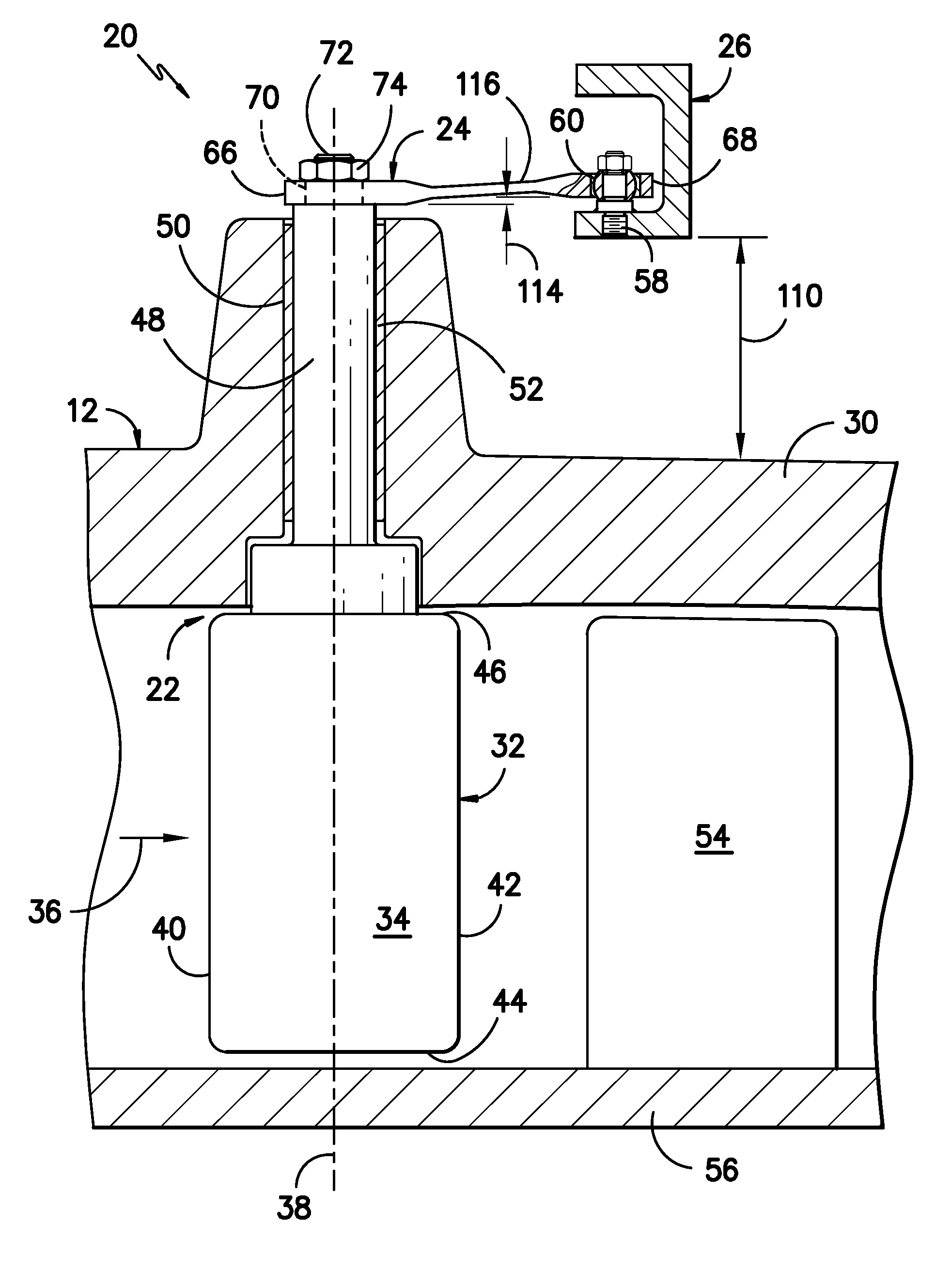
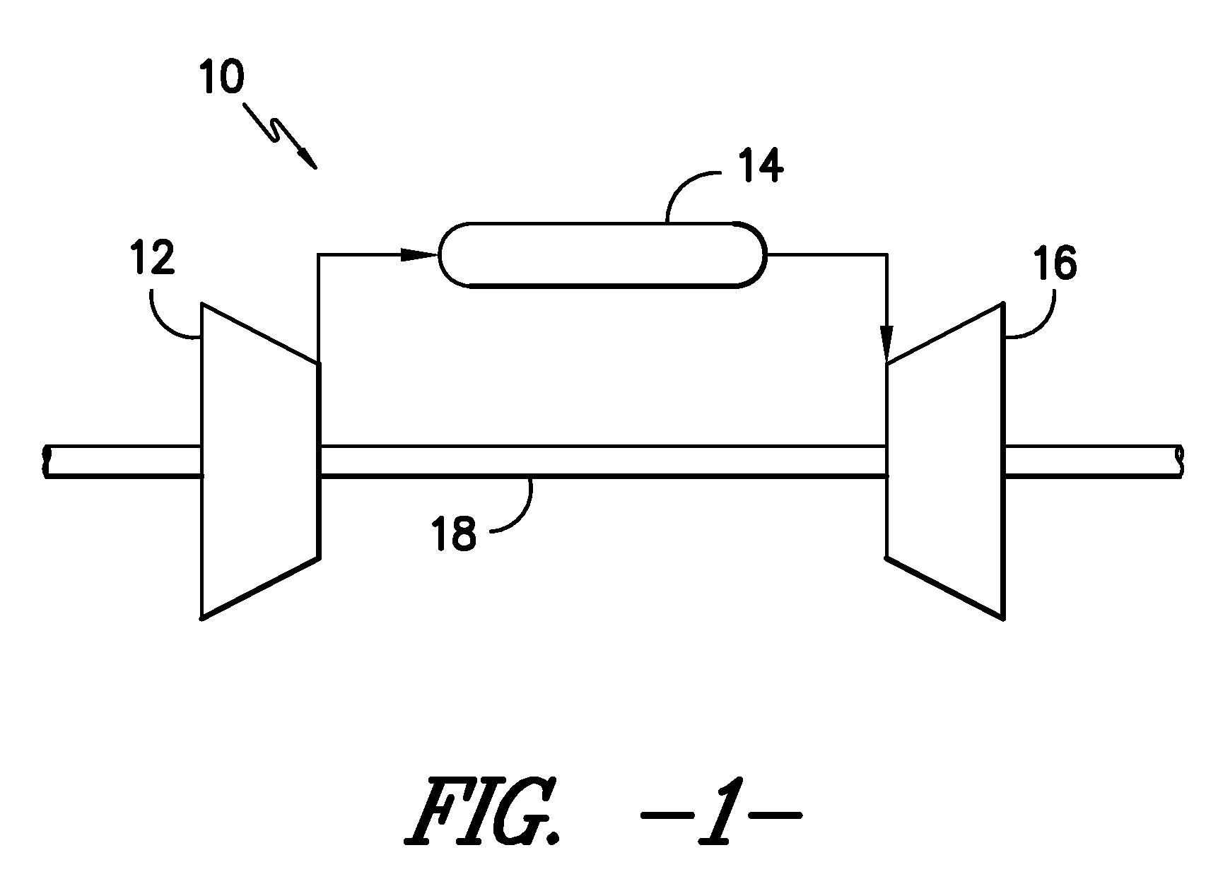
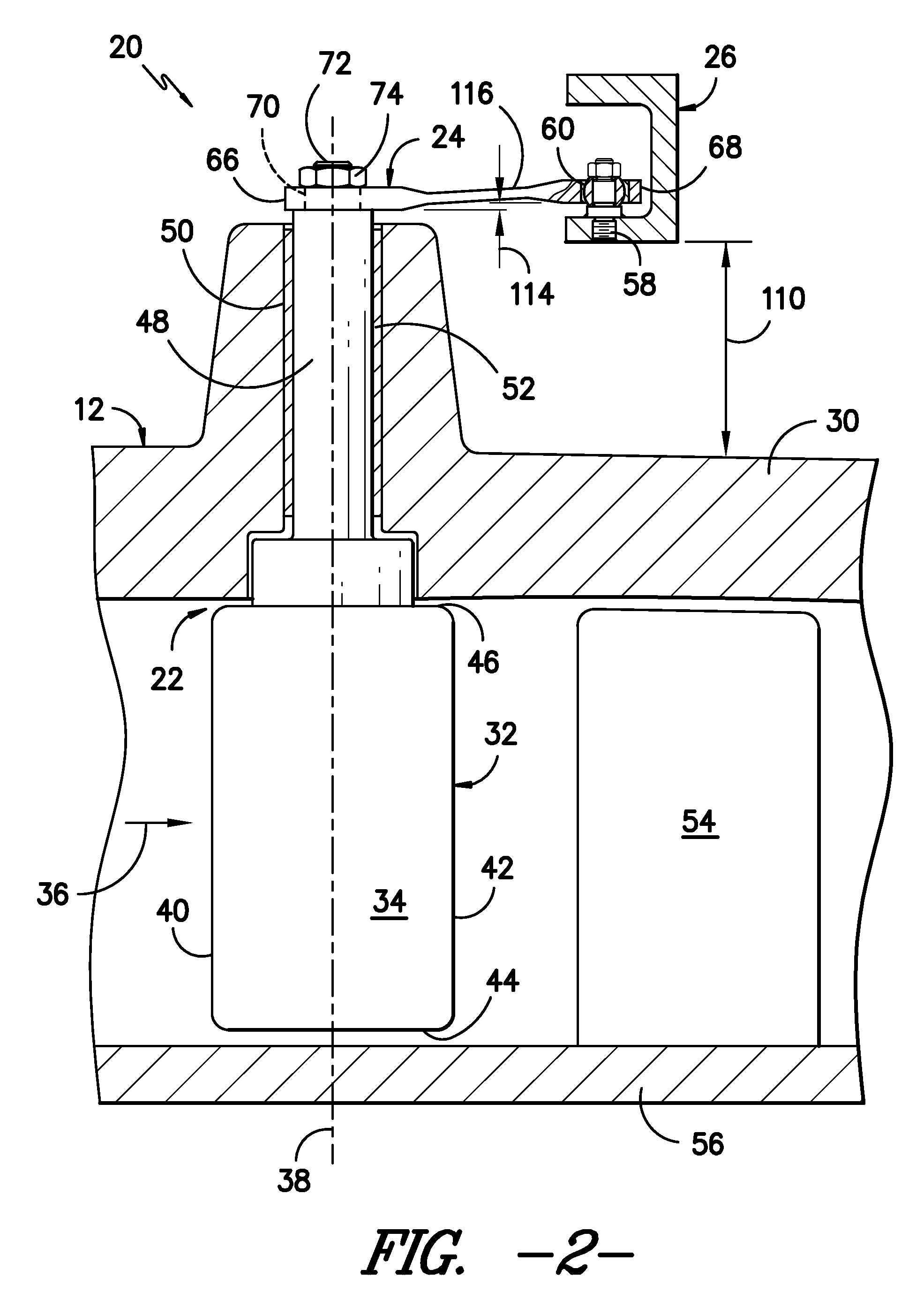
[0017]Referring to the drawings, FIG. 1 illustrates a schematic diagram of a gas turbine 10. The gas turbine 10 generally includes a compressor 12, a plurality of combustors 14, and a turbine section 16. The compressor 12 and turbine section 16 may generall...


PUM


Abstract

An attachment stud for a variable vane assembly is disclosed. The attachment stud may generally include a bottom segment, a middle segment, a top segment and a shoulder segment. The bottom segment may generally have a shape and configuration adapted to be secured to a synchronizing ring of the variable vane assembly. The middle segment may generally have a shape and configuration adapted to receive a rotational attachment device of the variable vane assembly. The shoulder segment may be disposed between the bottom segment and the middle segment. The top segment may generally have a shape and configuration adapted to receive a retaining device configured to rigidly attach the rotational attachment device to the attachment stud.

Description

FIELD OF THE INVENTION[0001]The present subject matter relates generally to gas turbines and, more particularly, to an attachment stud for a variable vane assembly of a compressor.BACKGROUND OF THE INVENTION[0002]Gas turbines typically include a compressor, a plurality of combustors, and a turbine section. The compressor pressurizes air flowing into the turbine. The pressurized air discharged from the compressor flows into the combustors. Air entering each combustor is mixed with fuel and combusted. Hot combustion gases flow from each combustor through a transition piece to the turbine section of the gas turbine to drive the turbine and generate power.[0003]A typical compressor for a gas turbine may be configured as a multi-stage axial compressor and may include both rotating and stationary components. A shaft drives a central rotor drum or wheel, which has a number of annular rotors. Rotor stages of the compressor rotate between a similar number of stationary stator stages, with ea...

Claims


Application Information

Patent Timeline
Patent Type & Authority Patents(United States)
IPC IPC(8): F01D17/16
CPCY02T50/671F16B5/0275F01D17/162Y02T50/60
Inventor JARRETT, JR., HARRY MCFARLANDLAMMAS, ANDREW JOHNHOWARD, MICHAEL CHRISTOPHER
Owner GE INFRASTRUCTURE TECH INT LLC
Learn More