Image processing apparatus and method using forward and inverse local adaptation processing and dynamic range processing
a local adaptation and image processing technology, applied in the field of image processing, can solve the problems of shadow-detail loss, highlight-detail loss, shadow-detail loss,
- Summary
- Abstract
- Description
- Claims
- Application Information
AI Technical Summary
Problems solved by technology
Method used
Image
Examples
first embodiment
[Configuration of Apparatus]
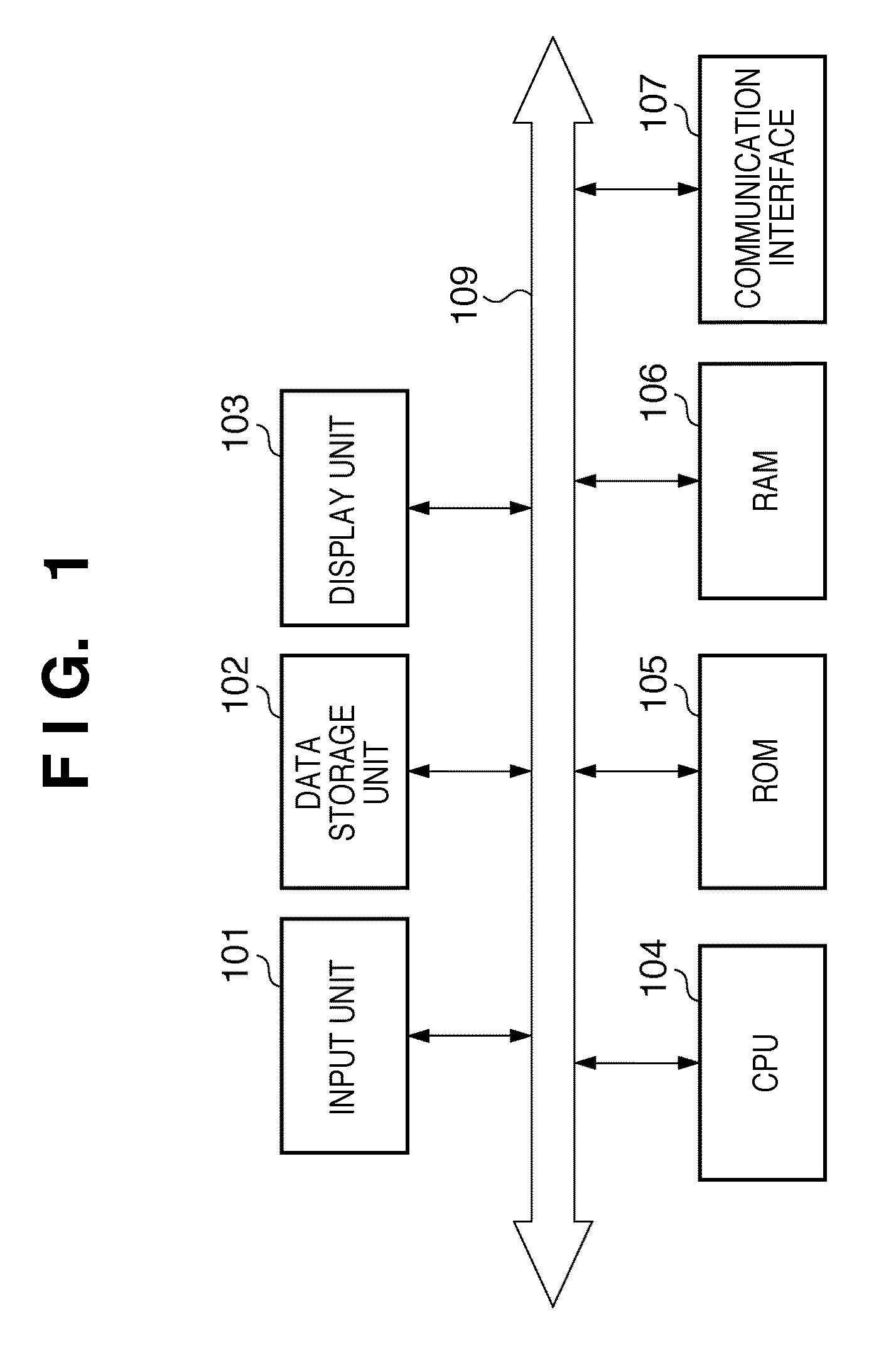
[0030]FIG. 1 is a block diagram illustrating the configuration of an image processing apparatus according to an embodiment of the present invention.
[0031]A microprocessor (CPU) 104 employs a random-access memory (RAM) 106 as a work memory and executes a program that has been stored in a memory such as a read-only memory (ROM) 105 and the like. The CPU 104 controls these components via a system bus 109 to execute image processing described later. The ROM 105 stores a program and data necessary for controlling the image processing apparatus as well as a program for image processing described later.
[0032]An input unit 101 is a keyboard and pointing device for accepting input of designations and data from a user. A mouse, track ball, track pad and tablet can be mentioned as examples of the pointing device. In a case where this embodiment is applied to a device such as a digital camera or printer, the input unit 101 may be buttons, numeric keys or a model dial...
second embodiment
[0138]Image processing according to a second embodiment of the present invention will now be described. Components in the second embodiment similar to those of the first embodiment are designated by like reference characters and need not be described again in detail.
[0139]In the example described in the first embodiment, only the maximum luminance Lm capable of being input by the input device is used by reason of the fact that the input device profile is assumed to contain at least the information representing the maximum luminance Lm capable of being input. In the second embodiment, a case where the input device profile further contains information representing the tone characteristic of the input device will be described.
[0140]In the example described in the first embodiment, linearity of the input signal values is assumed or, in a case where the input signal values are non-linear, processing is executed upon linearizing these values using a gamma conversion or the like. In an act...
embodiments
Modification of Embodiments
[0144]In the embodiments set forth above, the description assumes that the aspect ratio of the captured image 220 is maintained in the reproduced image 301. Owing to the particulars of the display, however, there are also cases where the aspect ratio is not maintained. In such cases processing for changing the aspect ratio is added on between steps S703 and S704 in the processing shown in FIG. 8.
[0145]Furthermore, a filter having a circular region of interest has been described as a filter for extracting low-frequency components. In a case where the aspect ratio is changed, information representing the change in aspect ratio is stored in the viewing condition profile and the region of interest of the filter in the local adaptation processing on the output side is controlled in accordance with such profile.
[0146]FIG. 14 is a diagram illustrating the relationship between a change in aspect ratio of an image and shape of an adaptive visual field.
[0147]In FIG....
PUM
 Abstract
Description
Claims
Application Information
 - R&D
- Intellectual Property
- Life Sciences
- Materials
- Tech Scout
- Unparalleled Data Quality
- Higher Quality Content
- 60% Fewer Hallucinations
Browse by: Latest US Patents, China's latest patents, Technical Efficacy Thesaurus, Application Domain, Technology Topic, Popular Technical Reports.
© 2025 PatSnap. All rights reserved.Legal|Privacy policy|Modern Slavery Act Transparency Statement|Sitemap|About US| Contact US: help@patsnap.com


