
Post ram

a technology of rams and posts, applied in the field of post rams, can solve the problems of structural failure, hollow metal tubes of adjustable columns, and inability to easily cut metal tubes to fit within an extremely short span, and achieve the effect of convenient siz

Inactive Publication Date: 2014-03-04
WEDDLE TOOL
View PDF15 Cites 9 Cited by
  • Summary
  • Abstract
  • Description
  • Claims
  • Application Information

AI Technical Summary

Benefits of technology

The invention is a temporary support for building structures that is strong, adjustable, and easy to install. It can be used in construction and remodeling projects, large or small. The support can be used to correct sagging floors, level and support recreational vehicles or manufactured homes, or support high-weight appliances. The support is portable, lightweight, inexpensive, and dependable in use. The technical effects of the invention are improved features and arrangements in a post ram that make it easier to install and use in building construction.

Problems solved by technology

First, the metallic tube of an adjustable column is hollow and can bend if it is not properly placed.
Second, the metallic tube cannot be easily cut to fit within an extremely short span.
Also, when the weight of a structure is placed on an adjustable column, stresses within the threaded rod can exceed design limits resulting in structural failures.
Additionally, many users do not provide footings of sufficient size and strength beneath adjustable columns.
Many users simply place the column on a wood or concrete floor thereby causing the floor to crack.
Finally, adjustable columns are not capable of operating without the use of additional tools.
If a user lacks an appropriate wrench, or is unable to turn the threaded rod with a wrench in a tight spot, an adjustable column cannot be utilized.

Method used


Image

  • Post ram
  • Post ram
  • Post ram

Examples


Embodiment Construction

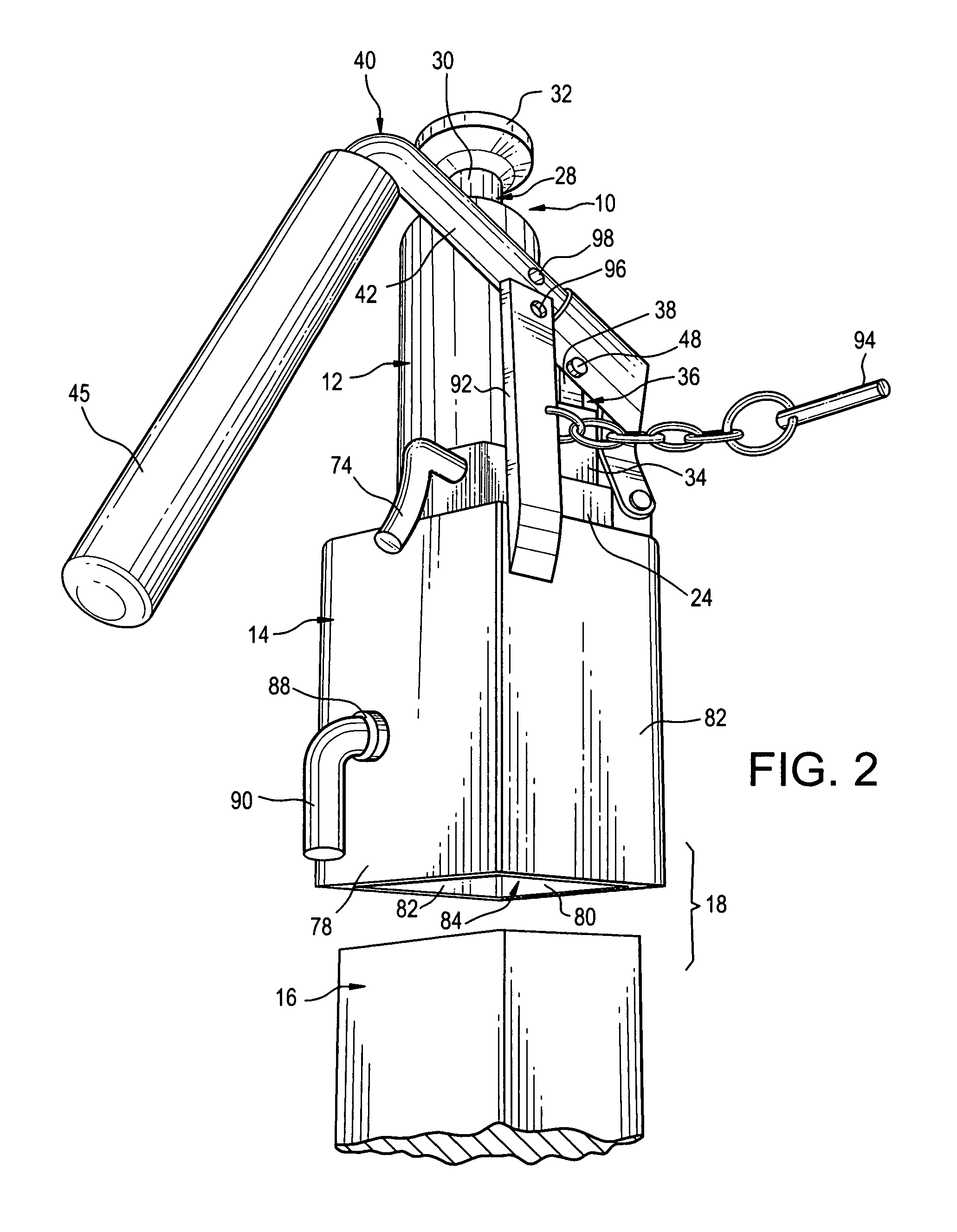
[0017]Referring now to the FIGS., a post ram in accordance with the present invention is shown at 10. The post ram 10 includes a bottle jack 12 affixed atop a socket member 14. The socket member 14 is sized to snugly receive one end of a wooden post 16 therein. When joined together, the post ram 10 and post 16 define a temporary support 18 that is useful in a variety of settings.

[0018]The bottle jack 12 includes a reservoir 20, containing a measured quantity of hydraulic oil 22 affixed atop a base plate 24. A main cylinder 26 is affixed within the reservoir 20 and has an opening 28 located at the top of the reservoir 20. A main piston 30 is slidably positioned within the main cylinder 26 and can be selectively extended from the opening 28. A wide, load-bearing plate 32 is affixed to the free end of the main piston 30 outside the main cylinder 26.

[0019]A pump cylinder 34 is affixed atop the base plate 24 adjacent the reservoir 20. The pump cylinder 34 has an open top 36. A pump pisto...


PUM


Abstract

A post ram is disclosed herein. The post ram includes a socket member that is configured to receive one end of a wooden post. A thumbscrew threadably engages, and penetrates, the socket member for selectively securing the wooden post within the socket member. A bottle jack is affixed atop the socket member.

Description

FIELD OF THE INVENTION[0001]The present invention relates generally to implements for applying pushing or pulling force utilizing fluid pressure.BACKGROUND OF THE INVENTION[0002]During reconstruction projects, carpenters frequently substitute temporary supports for load-bearing walls to keep buildings sound. When the walls are rebuilt or replaced by other structures, the supports are removed and set aside for reuse thereby minimizing waste and reducing costs.[0003]An adjustable column is a common type of temporary support. Such a column includes a rigid, metallic tube having a load-bearing plate affixed to one of its ends and a threaded rod screwed into the other one of its ends. Usually, a second, load-bearing plate is affixed to the free end of the threaded rod. By turning the rod with a wrench, the length of an adjustable column can be varied for a custom fit between a floor and a ceiling.[0004]Adjustable columns have drawbacks. First, the metallic tube of an adjustable column is...

Claims


Application Information

Patent Timeline
Patent Type & Authority Patents(United States)
IPC IPC(8): B66F7/04
CPCB66F3/42B66F3/25
Inventor WEDDLE, DAVID, R.
Owner WEDDLE TOOL
Learn More