Eureka AIR delivers breakthrough ideas for toughest innovation challenges, trusted by R&D personnel around the world.

Modular lighting system and method employing loosely constrained magnetic structures

a magnetic structure and module technology, applied in the field of module lighting, can solve the problems of limiting the power capacity of general illumination applications, and affecting the performance of lighting systems

Inactive Publication Date: 2014-02-18
APEX TECH INC
View PDF58 Cites 83 Cited by
  • Summary
  • Abstract
  • Description
  • Claims
  • Application Information

AI Technical Summary

Benefits of technology

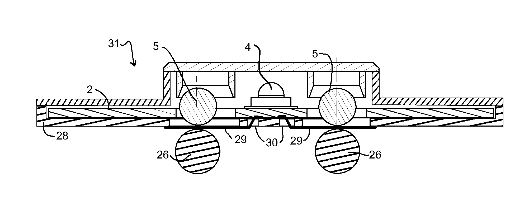
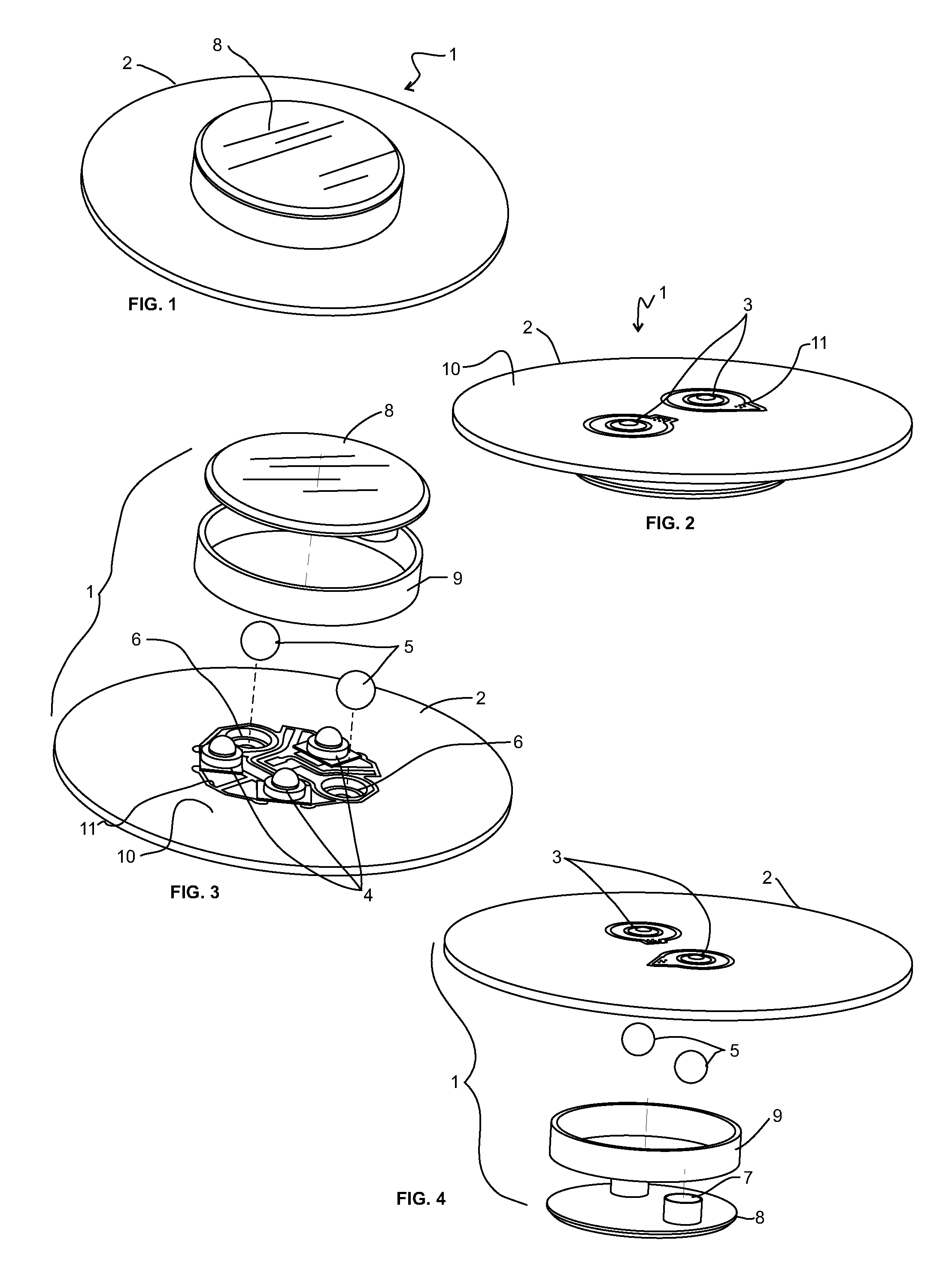
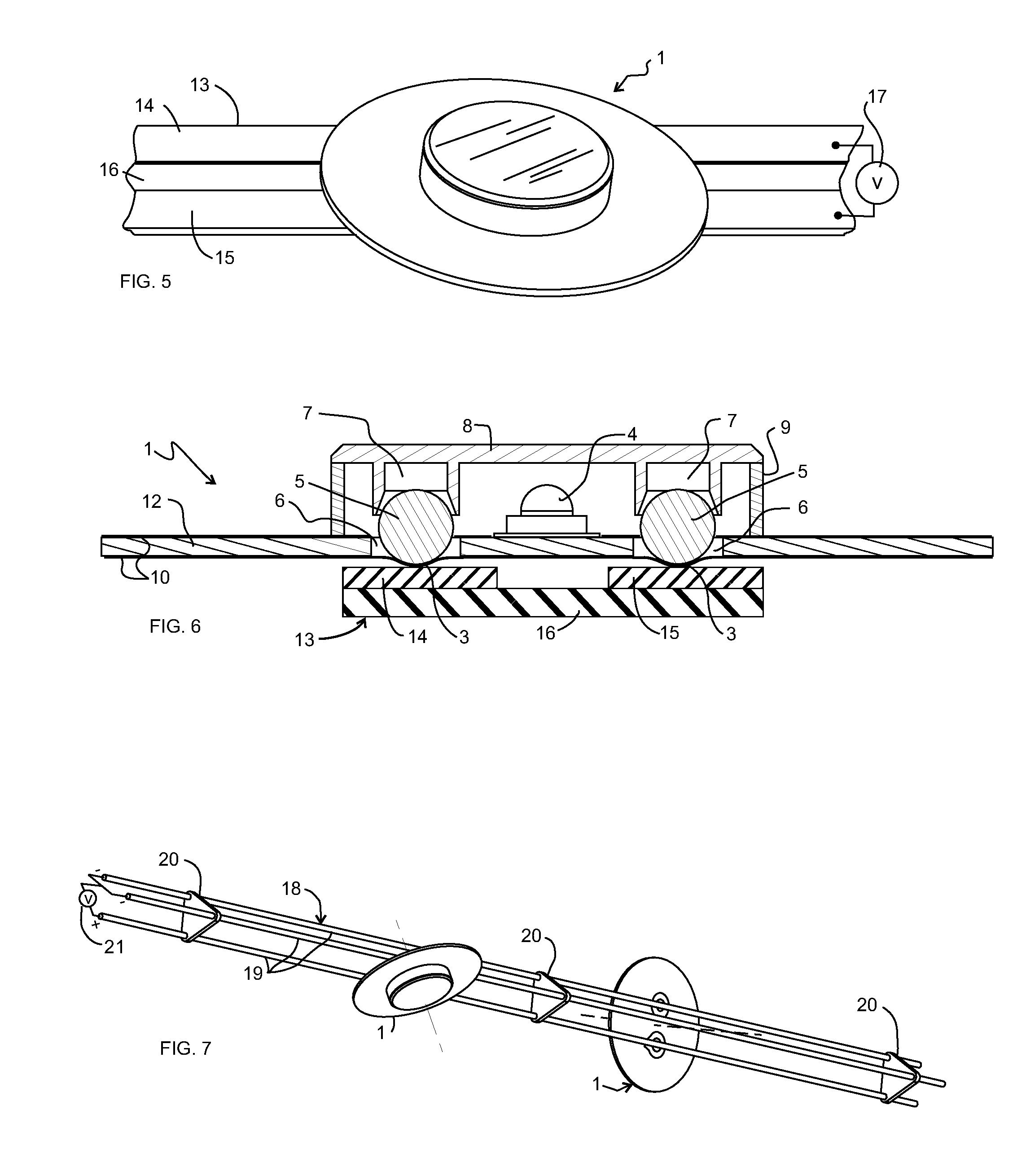
[0016]The present invention relates to the discovery and invention wherein a magnetic connection also includes the electrical connection between a lighting module and a lighting fixture without requiring mechanical precision where parts interface. In further embodiments, the inclusion of a heat sink for removing heat further improves the present invention.

Problems solved by technology

Existing magnetic attachment systems have limited thermal cooling efficiencies which restrict their power capability for general illumination applications with high-brightness LED assemblies since the greater the number of LEDs, the greater the heat generation and the greater the degradation problem.
Excess thermal interfaces in the conduction path between the LED subassembly and the external heat sink generally add to cooling inefficiencies.
Also, the number of electrical contacts that can be attached uniformly is limited.
Available one-piece standard screw-in incandescent bulb replacements using solid state lighting combine less reliable electrolytic capacitors with higher reliability and more expensive LED subassemblies in a single field replaceable unit.
Differences in functionality such as dimming in the integrated electronics result in stocking completely different units or including unused functionality and unnecessary parts cost.
Although two piece designs have been proposed, these proposals have not provided details on how a mechanical, electrical, and thermally efficient mounting of the LED subassembly can be accomplished to the socket with higher modularity.
Even in current solid state lighting systems that are not meant to fit in an existing incandescent lighting fixture, differences in functional attributes including power output, emitted light spectral, or directional characteristics create increased costs to businesses and consumers.
Rapidly rising prices for rare earth elements has increased the cost of relatively strong magnets and as such, while useful, they are becoming impractical for lower cost lighting systems.
Existing lighting systems fail to simultaneously optimize the mechanical, electrical, and thermal performance especially with smaller, less expensive magnets which require the stronger magnets to properly make and retain a connection.
Insulation piercing contacts permanently change the system which may introduce aesthetic or safety issues when a module is removed or moved within the system.
Lighting modules can be difficult to seal from the environment while maintaining electrical / mechanical and thermal performance and this adds to the difficulties with magnetic attachment of an electrical connection for a lighting system.

Method used


Image

  • Modular lighting system and method employing loosely constrained magnetic structures
  • Modular lighting system and method employing loosely constrained magnetic structures
  • Modular lighting system and method employing loosely constrained magnetic structures

Examples


Embodiment Construction

[0089]While this invention is susceptible to embodiment in many different forms, there is shown in the drawings and will herein be described in detail specific embodiments, with the understanding that the present disclosure of such embodiments is to be considered as an example of the principles and not intended to limit the invention to the specific embodiments shown and described. In the description below, like reference numerals are used to describe the same, similar or corresponding parts in the several views of the drawings. This detailed description defines the meaning of the terms used herein and specifically describes embodiments in order for those skilled in the art to practice the invention.

[0090]The terms “a” or “an”, as used herein, are defined as one or as more than one. The term “plurality”, as used herein, is defined as two or as more than two. The term “another”, as used herein, is defined as at least a second or more. The terms “including” and / or “having”, as used he...


PUM

PropertyMeasurementUnit
thicknessaaaaaaaaaa
separation distanceaaaaaaaaaa
diameteraaaaaaaaaa

Abstract

A lighting system including modules containing LEDs or other electroluminescent devices and loosely constrained magnetic structures at least partially contained within cavities in the module substrate that are connected to fixtures under magnetic force. The loosely constrained magnetic structures accommodate mechanical variations in the system and provide a method to connect modules mechanically, electrically and thermally to different fixtures or positions in fixtures without tools. The relatively short distance separating magnetic structures provides high connection forces with the use of relatively small magnets. Magnets and electrical contacts are not located directly between the LED subassembly and the fixture, which provides higher thermal conductivity pathways to remove heat from the LEDs. Biasing members may be used to increase thermal contact. Magnetic structures may, but are not required, to conduct electricity. Fixtures that attach to modules include rails, sockets, heat sinks and two-dimensional structures with recessed electrodes for improved electrical safety.

Description

[0001]This application is a continuation-in-part of U.S. non-provisional application Ser. No. 12 / 698,731 filed on Feb. 2, 2010 which claims priority of U.S. provisional application No. 61 / 206,609, filed on Feb. 2, 2009 and U.S. provisional application No. 61 / 279,391 filed on Oct. 20, 2009; and U.S. provisional application No. 61 / 402,588 filed on Sep. 1, 2010; U.S. provisional application No. 61 / 456,921 filed on Nov. 15, 2010; and U.S. provisional application No. 61 / 514,017 filed on Aug. 1, 2011, all of which are included herein in their entirety by reference.COPYRIGHT NOTICE[0002]A portion of the disclosure of this patent contains material that is subject to copyright protection. The copyright owner has no objection to the reproduction by anyone of the patent document or the patent disclosure as it appears in the Patent and Trademark Office patent files or records, but otherwise reserves all copyright rights whatsoever.BACKGROUND OF THE INVENTION[0003]1. Field of the Invention[0004]...

Claims


Application Information

Patent Timeline
Patent Type & Authority Patents(United States)
IPC IPC(8): F21V21/00F21V29/00
CPCF21V21/35H05K1/0203F21V29/2231H05K2201/10106F21S2/005F21Y2101/02F21V29/246F21V15/011F21V23/005F21V21/096H05K3/325F21Y2105/001H05K2201/083F21V29/004Y10T29/49117F21V29/773F21V29/89F21V29/507F21V29/70F21Y2105/10F21Y2115/10
Inventor RUDISILL, CHARLES A.WHITTLE, DANIEL JOHN
Owner APEX TECH INC
Why Eureka
Eureka Blog
Learn More