
Tow strap apparatus

Inactive Publication Date: 2014-02-18
HUANG HAN CHING
View PDF13 Cites 13 Cited by
  • Summary
  • Abstract
  • Description
  • Claims
  • Application Information

AI Technical Summary

Benefits of technology

The present invention is a light tow strap apparatus that aims to wind the tow strap quickly. This is the main objective of the invention, which has technical effects that allow for faster and more efficient use of the tow strap.

Problems solved by technology

However, it is troublesome to reel the tow strap when the tow strap is not in use.
A large coil spring requires a lot of steel which is heavy and expensive.

Method used


Image

  • Tow strap apparatus
  • Tow strap apparatus
  • Tow strap apparatus

Examples


Embodiment Construction

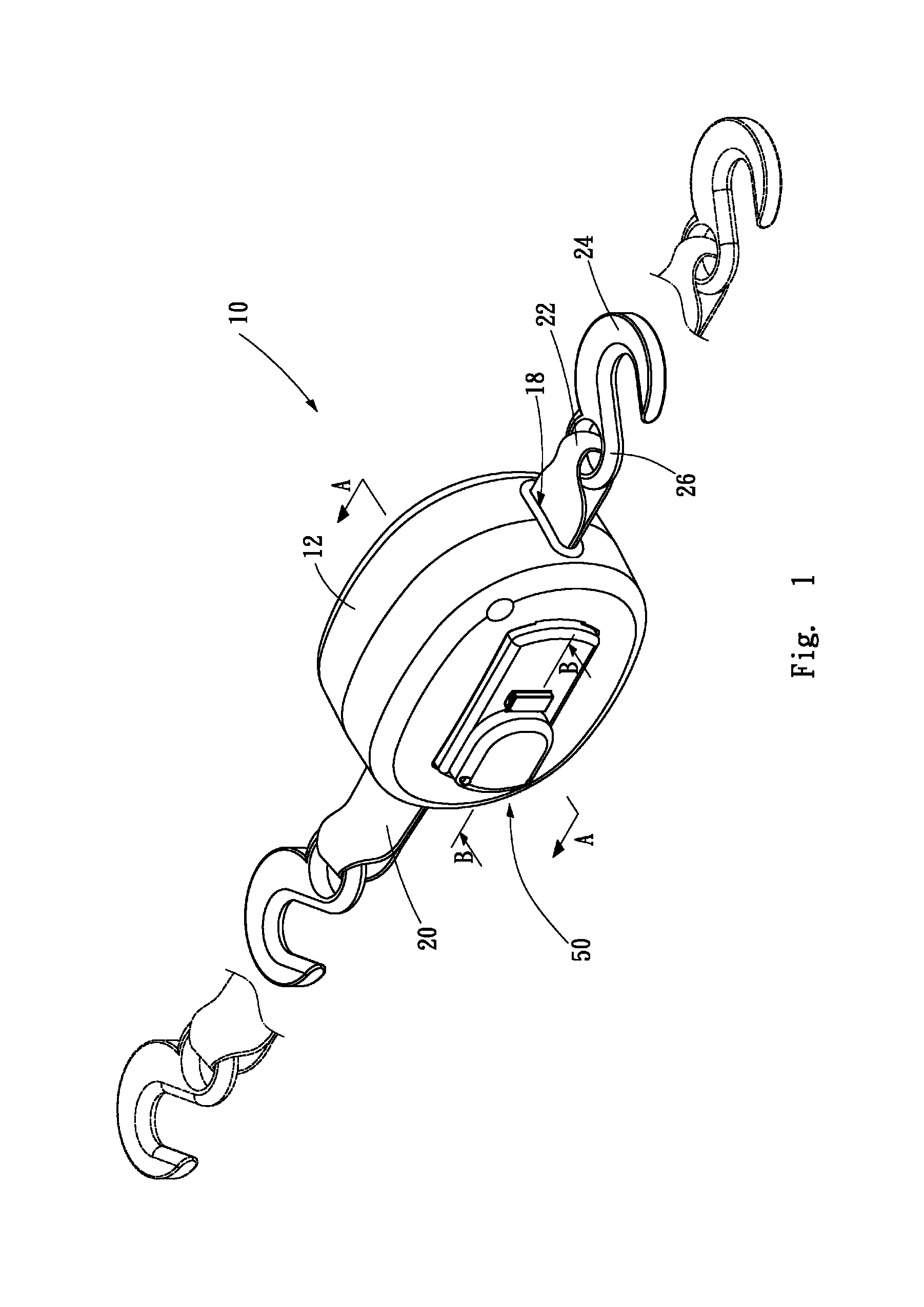
[0022]Referring to FIGS. 1 to 6, a tow strap apparatus 10 according to a first embodiment of the present invention is shown. Referring to FIG. 1, the tow strap apparatus 10 includes a tow strap 20, a casing 12, a reel 31, a driving unit 50 and a speed-increasing gearbox 40.

[0023]The casing 12 includes two halves each including an aperture 11 defined therein, a cavity 13 defined in an external side (FIG. 4), and two opposite cutouts 16 defined in the edge thereof. By screws 14, the halves of the casing 12 are joined so that the cutouts 16 form two opposite slots 18. One of the halves of the casing 12 further includes two opposite apertures 15 in communication with the cavity 13 (FIG. 6).

[0024]The reel 31 includes an axle 30 and two discs 38. Each of the discs 38 includes a hub 33 formed thereon and an aperture 35 defined in the hub 33. The axle 30 includes a slot 32 defined therein, a butt 34 formed at an end, and an annular groove defined near an opposite end. The axle 30 is fit in ...


PUM


Abstract

A tow strap apparatus includes a casing, a reel, a tow strap, a driving unit and a speed-increasing gearbox. The reel is rotationally placed in the casing. The tow strap is reeled on the reel. The driving unit is supported on the casing. The speed-increasing gearbox connects the driving unit to the reel.

Description

BACKGROUND OF INVENTION[0001]1. Field of Invention[0002]The present invention relates to a tow strap and, more particularly, to a tow strap apparatus equipped with a speed-increasing gearbox.[0003]2. Related Prior Art[0004]A vehicle sometimes breaks or gets stuck in the sand, mud or snow. To get such a vehicle out of the trouble, it can be tied to another vehicle via a rope or tow strap. The first vehicle can be towed and rescued by the second vehicle.[0005]A tow strap is often made of woven fabric and made of an adequate length. However, it is troublesome to reel the tow strap when the tow strap is not in use.[0006]As disclosed in U.S. Pat. No. 7,942,360, a conventional tow strap apparatus 10 includes a casing 12, a tow strap 16, a reel 28 and two coil springs 50. The casing 12 includes two opposite apertures 15 defined therein. The tow strap 16 includes two hooks 20 tied to a webbing 18. The reel 28 includes a hub 36 that includes two halves. Teeth 40 are formed on each half of th...

Claims


Application Information

Patent Timeline
IPC IPC(8): B60D1/18
CPCB60D1/185B60D1/18
Inventor HUANG, HAN-CHING
Owner HUANG HAN CHING
Learn More