
Tent assembly

a technology for tents and components, applied in the field of tent constructions, can solve problems such as damage to tents, and achieve the effect of significantly facilitating the assembly of structures and increasing the strength of the overall structur

Active Publication Date: 2013-12-10
SLINGFIN
View PDF17 Cites 14 Cited by
  • Summary
  • Abstract
  • Description
  • Claims
  • Application Information

AI Technical Summary

Benefits of technology

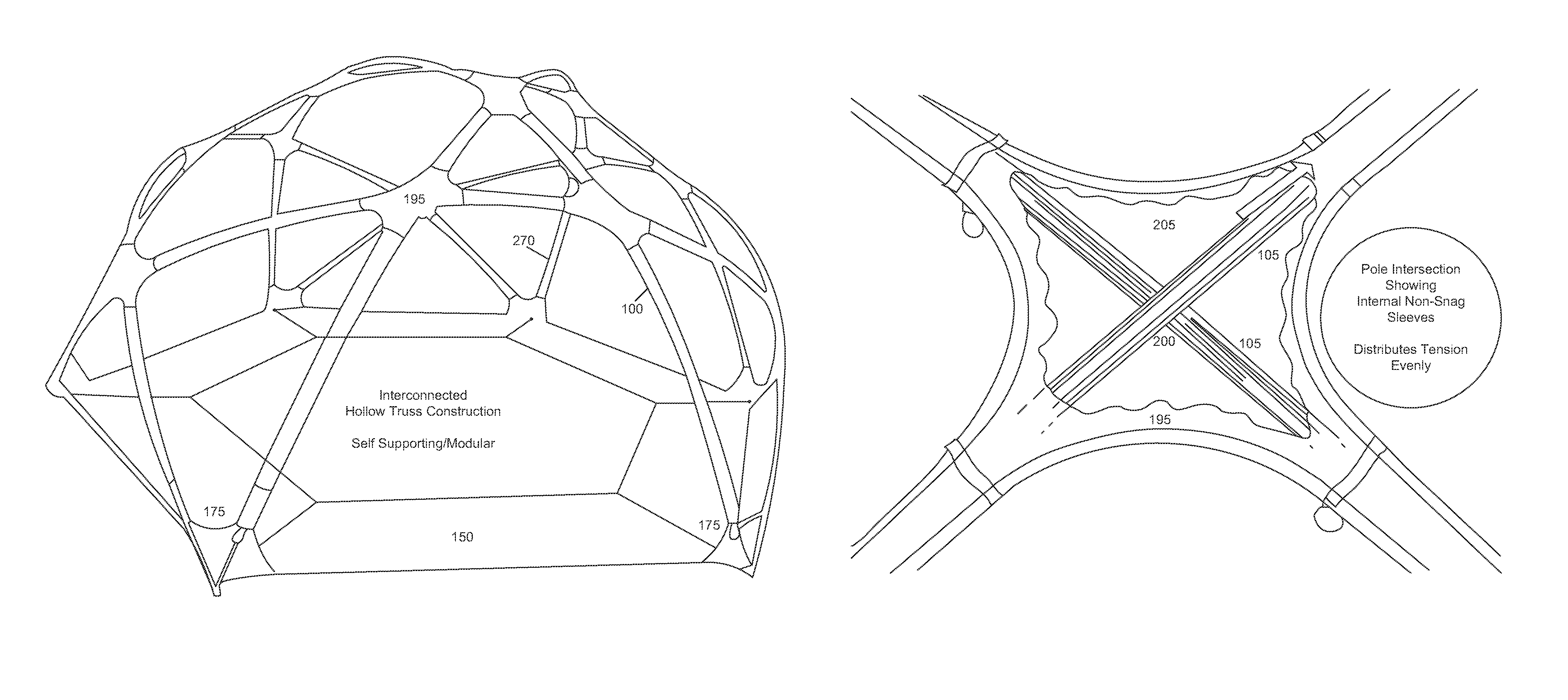
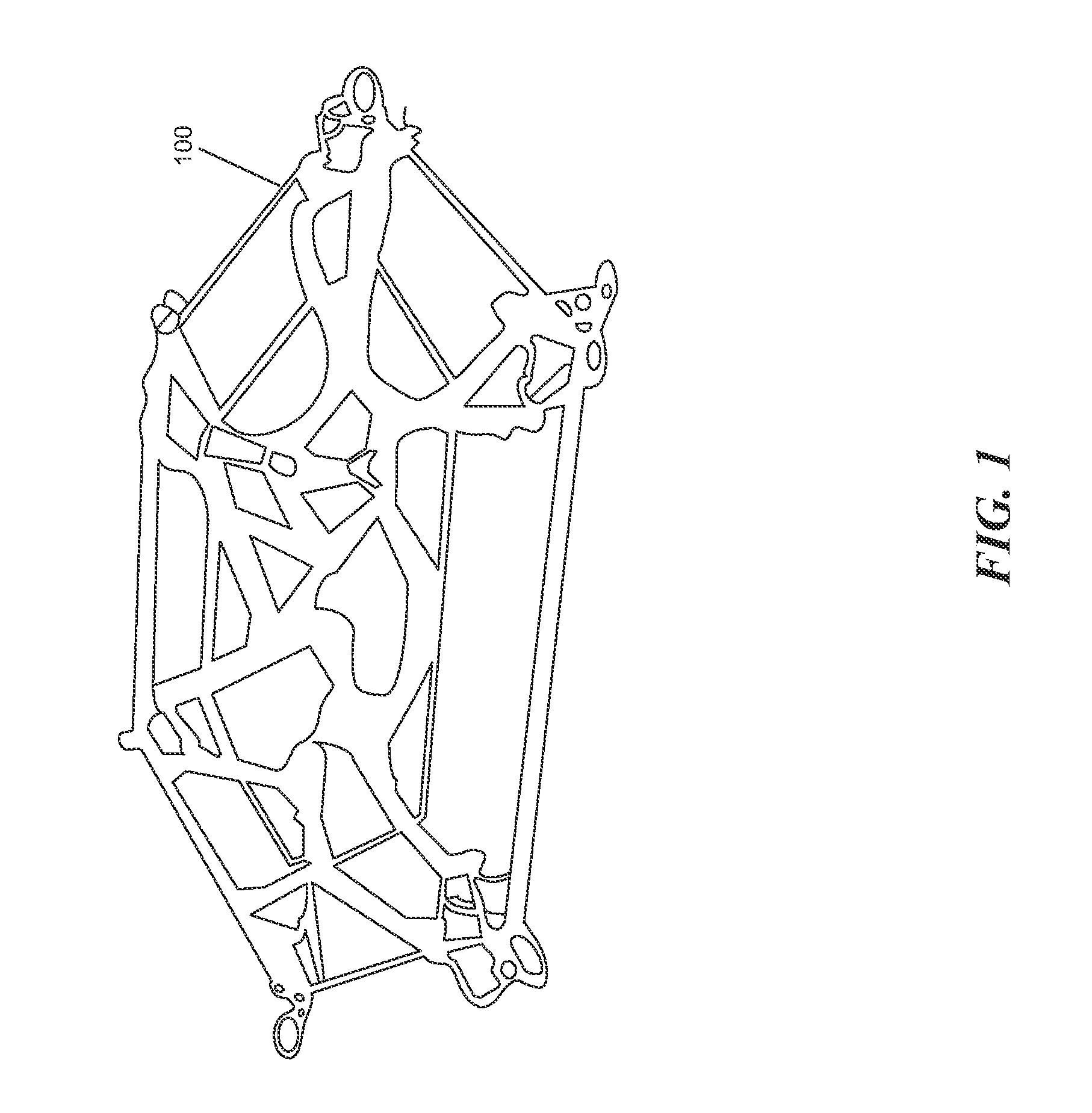
[0004]In at least one embodiment, the techniques described herein relates to a structure and method of assembling and positioning compression members using a singular or plurality of flexible hollow sleeve structures with integral fabric hub intersections that are held in tension in combination with compression members that can be used for a variety of applications. The present invention makes assembling structures significantly easier than known prior art since the intersecting flexible hollow sleeve structures can be made continuous. This allows users to erect the structure without the need for additional help. In addition, the improved tent assembly discussed herein is significantly stronger when deployed with compression members because the hollow sleeve structures, with integral fabric hub intersections, can be tensioned, thus significantly increasing the strength of the overall structure.
[0005]In embodiments, a further advantage of the improved tent assembly includes ease of assembly in, for example, high wind conditions. The web truss of the disclosed tent assembly may be set up merely with the tent poles without a need for a flysheet and / or a tent body. The pole sleeves of the web truss may be tensioned merely using provisions of the web truss it self, at which time the tent assembly is at full strength even before the flysheet and / or tent body is added. In embodiments, the tent assembly achieves complete structural integrity when the web truss is fitted with the poles. In prior art, since poles are added to the tent body or flysheet one at a time, high wind conditions often damage (e.g., snap) the poles and damage the tents, especially because complete structural integrity of the tent is not attained until the tent is fully erected with all tent poles in position.

Problems solved by technology

In prior art, since poles are added to the tent body or flysheet one at a time, high wind conditions often damage (e.g., snap) the poles and damage the tents, especially because complete structural integrity of the tent is not attained until the tent is fully erected with all tent poles in position.

Method used


Image

  • Tent assembly
  • Tent assembly
  • Tent assembly

Examples


Embodiment Construction

[0024]Various examples of the invention will now be described. The following description provides specific details for a thorough understanding and enabling description of these examples. One skilled in the relevant art will understand, however, that the invention may be practiced without many of these details. Likewise, one skilled in the relevant art will also understand that the invention can include many other obvious features not described in detail herein. Additionally, some well-known structures or functions may not be shown or described in detail below, so as to avoid unnecessarily obscuring the relevant description.

[0025]The terminology used below is to be interpreted in its broadest reasonable manner, even though it is being used in conjunction with a detailed description of certain specific examples of the invention. Indeed, certain terms may even be emphasized below; however, any terminology intended to be interpreted in any restricted manner will be overtly and specific...


PUM

PropertyMeasurementUnit
volumeaaaaaaaaaa
interior volumeaaaaaaaaaa
tensionaaaaaaaaaa

Abstract

Disclosed are structures and methods of assembling and positioning an improved tent assembly where members of the assembly use flexible hollow sleeve structures with integral fabric hub intersections that are held in tension in combination with compression members that can be used for a variety of applications. Disclosed techniques make assembling tent assemblies significantly easier than known prior art since the intersecting flexible hollow sleeve structures can be made continuous. In addition, the improved tent assembly is significantly stronger when deployed with compression members because the hollow sleeve structures, with integral fabric hub intersections, can be tensioned, thus significantly increasing the strength of the overall structure.

Description

PRIORITY CLAIM[0001]This patent application claims priority to U.S. Provisional Patent Application No. 61 / 366,921, entitled “Flexible Hollow Sleeve Frame Support Structure with Integral Fabric Hub Intersections,” filed Jul. 22, 2010, which is incorporated herein in its entirety.FIELD OF INVENTION[0002]The present invention generally relates to tent constructions, and more specifically, to an improved tent assembly that can easily be erected by a user, where the improved tent assembly uses a web truss for providing an internal frame structure, where the web truss is a flexible hollow sleeve frame support structure with integral fabric hub intersections.BACKGROUND OF THE INVENTION[0003]Tents of conventional construction are typically time-consuming to erect. For example, tents with conventional internal frames require substantial effort by more than one person to place all the poles in position and then build a tent body around the pole structures. Some prior art tent assemblies allow...

Claims


Application Information

Patent Timeline
Patent Type & Authority Patents(United States)
IPC IPC(8): E04H15/36E04H15/42
CPCE04H15/44Y10T29/49826
Inventor ZEMITIS, MARTIN S.
Owner SLINGFIN
Learn More