
Method and apparatus for a railway wheel ultrasonic testing apparatus

a technology of ultrasonic testing and railway wheels, applied in the field of ultrasonic testing, can solve problems such as wheel failure, wheel failure, wheel weakening, etc., and achieve the effect of more accurate and reproducible ultrasonic test data and faster data collection ra

Active Publication Date: 2013-12-03
AMSTED RAIL CO INC
View PDF2 Cites 8 Cited by
  • Summary
  • Abstract
  • Description
  • Claims
  • Application Information

AI Technical Summary

Benefits of technology

The solution enables faster and more reproducible ultrasonic test data collection by mitigating dynamic instabilities, ensuring accurate and reliable detection of subsurface flaws in railway wheels, even with non-standard dimensional tolerances.

Problems solved by technology

Railway wheels are generally either wrought or cast steel, and despite strict quality control measures, may contain flaws resulting from the manufacturing process.
These flaws can potentially include voids, cracks, as well as inclusions, which can weaken the wheel and potentially lead to wheel failure.
Automated ultrasonic testing has been challenged, to some extent, by the size and weight of railway wheels (typically weighing from 700 to 1000 pounds) which can make the automated collection of accurate ultrasonic test data difficult.
Particularly problematic are railway wheels with dimensional tolerances that, although within an acceptable range for production purposes, hamper the automated collection of accurate test data.
These instabilities result in the deflection of the wheel from axial centerline rotation around the geometric center of the wheel in the test fixture.
This has proven problematic as the collection of accurate ultrasonic test data often requires maintaining a stable geometric orientation as the wheel rotates.

Method used


Image

  • Method and apparatus for a railway wheel ultrasonic testing apparatus
  • Method and apparatus for a railway wheel ultrasonic testing apparatus
  • Method and apparatus for a railway wheel ultrasonic testing apparatus

Examples


Embodiment Construction

[0022]Although this specification is directed to the testing of railway wheels, it should be understood that the testing apparatus and methods disclosed in this specification are equally applicable to other cast and forged wheels used in industries unrelated to the railway industry. Consequently, the description of the novel method and apparatus as it relates to railway wheels is for convenience only.

[0023]Railway Wheel Ultrasonic Testing Apparatus

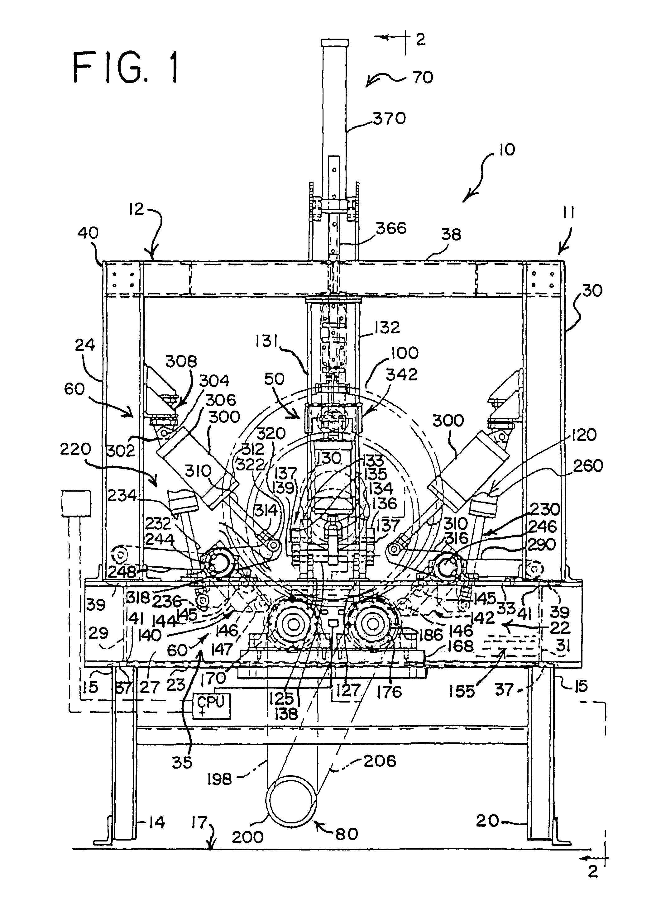
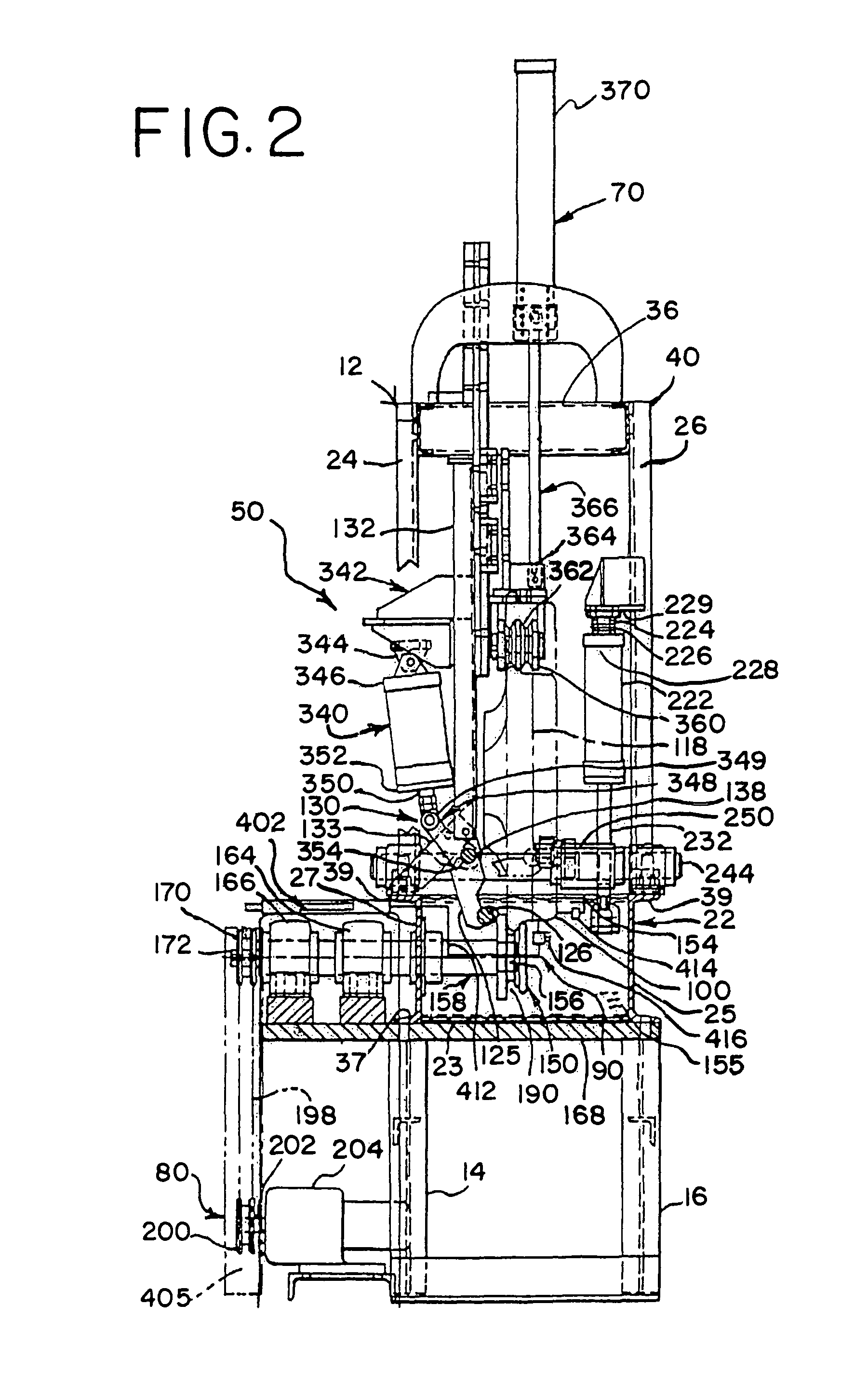
[0024]One embodiment of the ultrasonic testing apparatus is depicted in the front elevation view of FIG. 1 and the side elevation view of FIG. 2. The ultrasonic testing apparatus is designed for the nondestructive evaluation and subsurface mapping of the structure of a railway wheel 100 of the type exemplified by the illustration of FIG. 9.

[0025]The ultrasonic testing apparatus comprises, in one embodiment, the ultrasonic test fixture 11 for capturing and rotating the wheel and the ultrasonic sensing assembly 90. In addition, a CPU (e.g., ...


PUM

PropertyMeasurementUnit
weightaaaaaaaaaa
ultrasonic testaaaaaaaaaa
flexibilityaaaaaaaaaa

Abstract

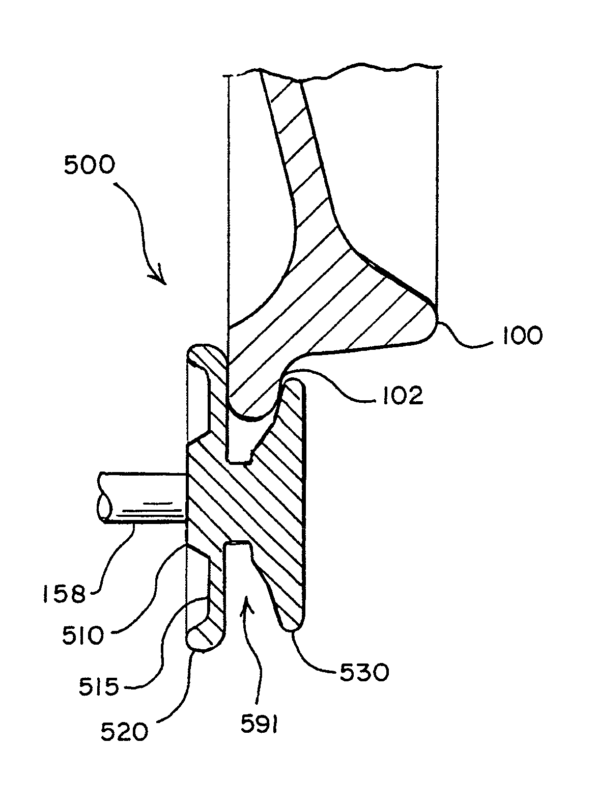
A method and apparatus for collecting ultrasonic test data from a railway wheel with an ultrasonic testing apparatus is described. The railway wheel is supported by two drive rollers, each having an indentation which engages with and rotates the wheel. An indexing transducer moves across the rotating wheel, collecting ultrasonic test data while a fixed transducer correlates a reference position on the wheel to the collected test data. To maintain the accuracy of the reference position to the collected test data, it is desirable to maintain the rotational stability of the wheel, minimizing any dynamic instability caused by dimensional tolerances in the wheel. To mitigate instabilities resulting from dimensional tolerances, the indentation of the drive rollers, which engage and drive the flange of the wheel, is adjustable by the flexing design of the drive rollers to maintain frictional contact between the wheel and the drive roller. This allows the indentation to accommodate the varying dimensional tolerances of the wheel flange, mitigating the possibility of dynamic instability resulting from departure of the wheel flange from the indentation.

Description

CROSS REFERENCE TO RELATED APPLICATIONS[0001]This application is related to U.S. Pat. No. 5,864,065, granted Jan. 26, 1999 to Prorok and entitled, “Test Apparatus for a Railway Wheel”, which is hereby incorporated by reference in its entirety.FIELD OF THE INVENTION[0002]This invention relates to ultrasonic testing, and more particularly, in one embodiment, to the ultrasonic testing of railway wheels.BACKGROUND OF THE INVENTION[0003]Railway wheels are generally either wrought or cast steel, and despite strict quality control measures, may contain flaws resulting from the manufacturing process. These flaws can potentially include voids, cracks, as well as inclusions, which can weaken the wheel and potentially lead to wheel failure. Ultrasound testing has been commonly employed to detect such flaws.[0004]Railway wheels ultrasonically analyzed by fixed position transducers typically examine the wheel and its underlying structure only at discrete, single locations around the perimeter of...

Claims


Application Information

Patent Timeline
Patent Type & Authority Patents(United States)
IPC IPC(8): G01N29/26
CPCB61K9/12G01N29/043G01N29/27G01M17/10G01N29/225G01N2291/2696
Inventor OLIVER, JOHN R.OLIVER, JOHN D.
Owner AMSTED RAIL CO INC
Learn More