Wedge drive

a drive and lug technology, applied in the direction of press rams, shaping tools, belts/chains/gearings, etc., to achieve the effect of simple and quick replacement and reduction of wear

Inactive Publication Date: 2013-11-05
VOESTALPINE GIESSEREI LINZ GMBH
View PDF17 Cites 5 Cited by
  • Summary
  • Abstract
  • Description
  • Claims
  • Application Information

AI Technical Summary

Benefits of technology

[0013]According to the invention, the wedge drive is composed of three main parts, namely a driver, the slider and the slider guide. These are accompanied by the usual accessories such as a forced return device, glide plates, and a spring, in particular a gas compression spring. The gas compression spring moves the slider back into the starting position when the press is raised; if the gas compression spring fails, the forced return device returns the slider to the starting position. The glide plates do not in fact have a vital task to perform for the function of the slider, but they do reduce the wear and can be simply and quickly replaced when worn. In addition, a so-called “lock-out” system is provided, which immobilizes the slider in the BDC position, i.e. the bottom dead center position of the slider.
[0014]According to the invention, instead of a bracket that connects the top and bottom parts of the slider to each other, a so-called connector strip is used, which reaches through openings in the slider bed side walls to engage the slider and hold it in the slider bed. As a result, the force transfer region is optimal, i.e., the force introduction points are much less far apart than in the case of a form-locked engagement with guide brackets, enabling narrower tolerances and also reducing changes to tolerances caused by thermal expansion. Because of the more advantageous design, the slider bed is more stable and it is possible to reduce costs.

Problems solved by technology

The glide plates do not in fact have a vital task to perform for the function of the slider, but they do reduce the wear and can be simply and quickly replaced when worn.

Method used


Image

  • Wedge drive
  • Wedge drive
  • Wedge drive

Examples


Embodiment Construction

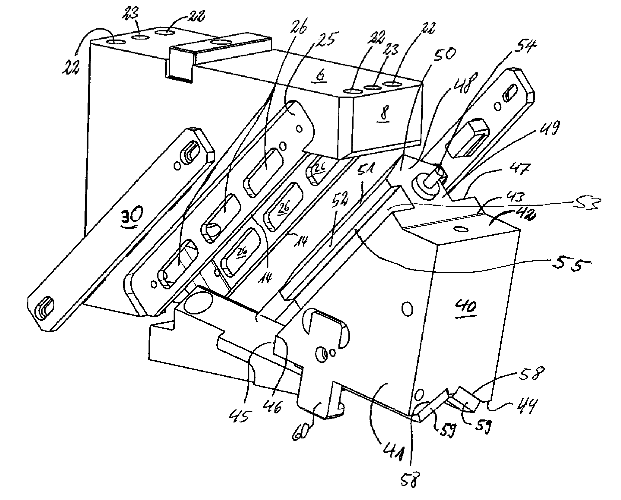
[0071]A wedge drive 1 according to the invention has a slider bed 2, a slider wedge 3, and a driver 4 as main components.

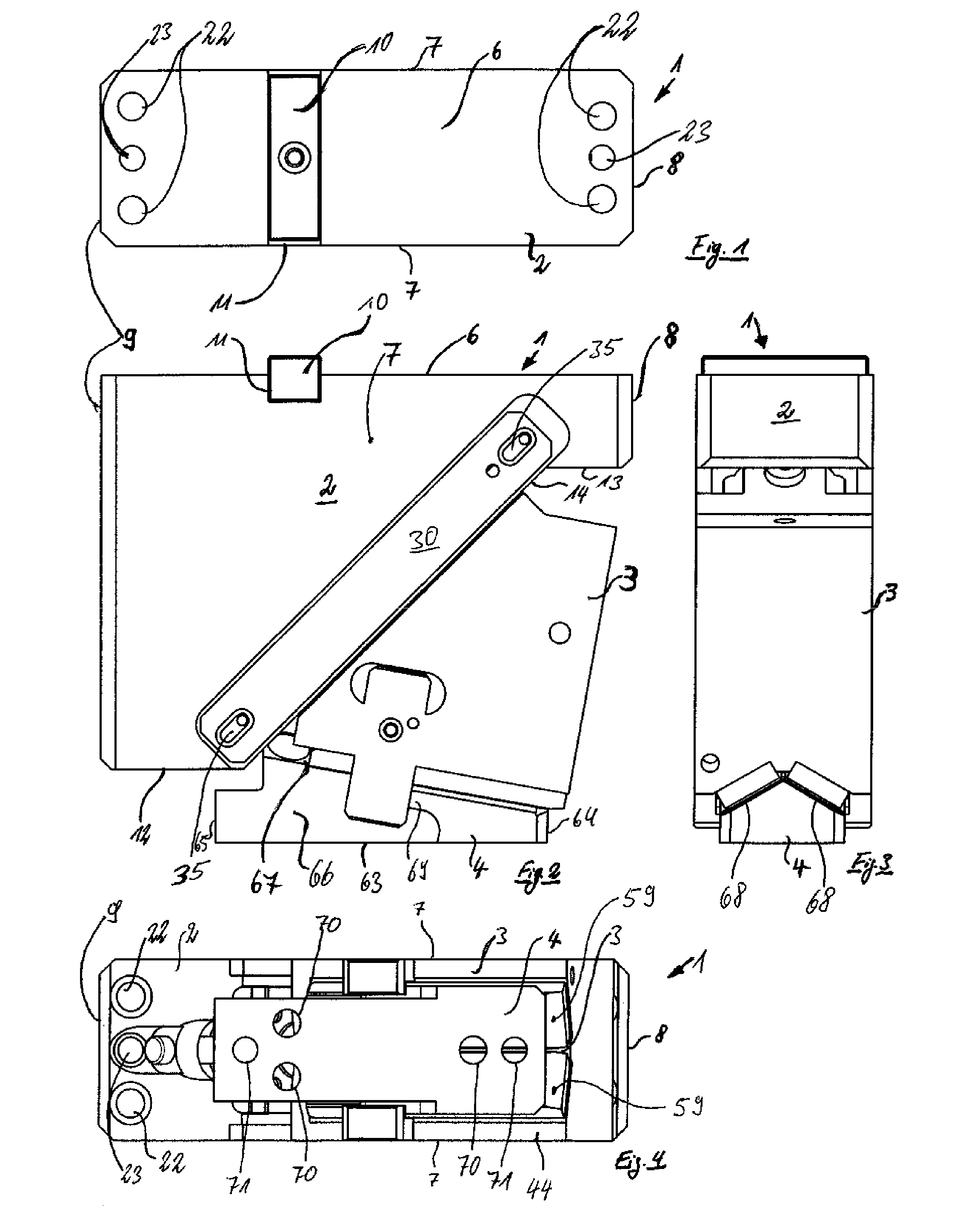
[0072]The slider bed 2 is box-shaped component with a top wall 6, side walls 7 extending orthogonally from it, a front end wall 8, and a back wall 9. The end wall 8 and the back wall 9 extend parallel to each other and orthogonal to the top wall 6 while the side walls 7 extend perpendicular or orthogonal to the top wall 6 and to the end wall 9 and back wall 9.

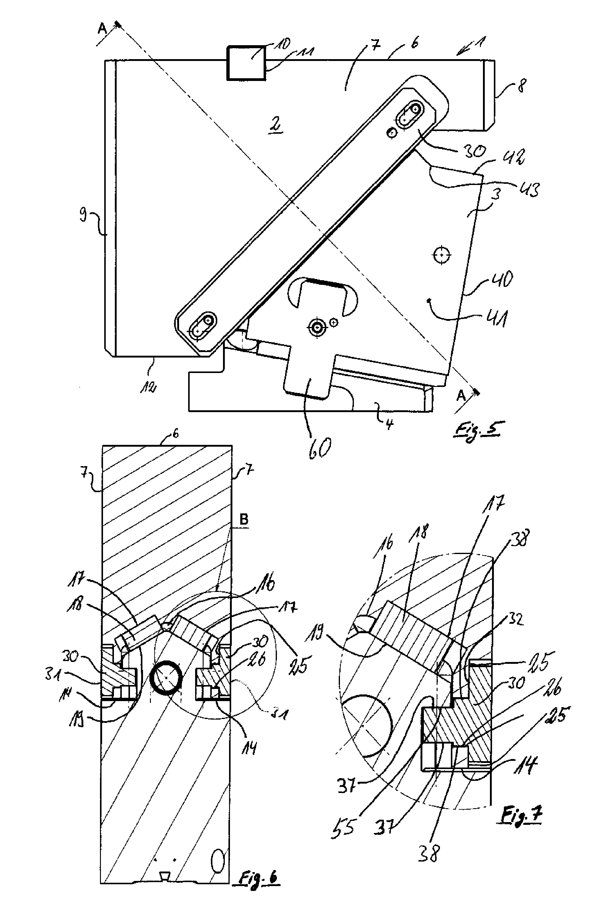
[0073]In the top wall 6, a feather key 10, which is for fitting the slider bed into a tool, is provided, which is embodied in the form of an elongated rectangle and is situated in a corresponding keyway 11 in the top wall 6.

[0074]Parallel to the top wall 6 and at a right angle to the side walls 7 and back wall 9, a bottom wall 12 extends away from an edge that it shares with the back wall 9.

[0075]Parallel to the back wall 9, the front end wall 8 extends from the top wall 6 for approximately ¼ the length of th...


PUM

PropertyMeasurementUnit
angleaaaaaaaaaa
vertical pressing forceaaaaaaaaaa
angleaaaaaaaaaa

Abstract

The invention relates to a wedge drive for converting a vertical pressing force, including at least one slider bed, one slider wedge, and one driver; to provide a movable coupling of the slider wedge in the slider bed, at least one bearing lug is provided; the bearing lug reaches through at least one bearing opening in a side wall of the slider bed from the outside and engages in a recess in the slider wedge; the slider wedge is supported on the bearing lug and the bearing lug is supported on a wall delimiting the bearing opening.

Description

FIELD OF THE INVENTION[0001]The invention relates to a wedge drive.BACKGROUND OF THE INVENTION[0002]Wedge drives are used in tools in metalworking, e.g. in presses. These wedge drives are usually connected to the devices that perform a stamping or other deformation procedure. A conventional wedge drive has an upper guide part, which includes a slider element and a slider guide element, and a lower guide part, which includes a driver element or vice versa. On the slider guide element side, the wedge drives are moved by a drive unit that exerts a generally vertical pressing force. On the driver element side, wedge drives are fastened to a base plate in the tool or press, onto which plate the work piece to be machined is also placed, either directly or by means of a corresponding support device.[0003]DE 26 40 318 B2 has disclosed a wedge drive for redirecting a vertical pressing force into a force acting at an angle thereto for the forming process. This wedge drive is composed of a dri...

Claims


Application Information

Patent Timeline
Patent Type & Authority Patents(United States)
IPC IPC(8): B21D5/04B26D5/18
CPCB21D28/32Y10T74/1892Y10T83/8853Y10T83/8841B30B1/40B30B15/06B21D37/08
Inventor LANKSWEIRT, JOCHEN
Owner VOESTALPINE GIESSEREI LINZ GMBH
Why Eureka
Try Eureka