Rackmount I/O signal protector assembly for surge protection
a signal protector and rackmount technology, applied in the direction of overvoltage protection resistors, emergency protective arrangements for limiting excess voltage/current, circuit arrangements, etc., can solve the problems of modern telecommunications related equipment susceptible to transient surges, protection devices were unable to provide over-voltage and over-current transient protection, and yet maintained 1 gigabit network data rates. , to achieve the effect of simple and economical manufacture and assembly
- Summary
- Abstract
- Description
- Claims
- Application Information
AI Technical Summary
Benefits of technology
Problems solved by technology
Method used
Image
Examples
second embodiment
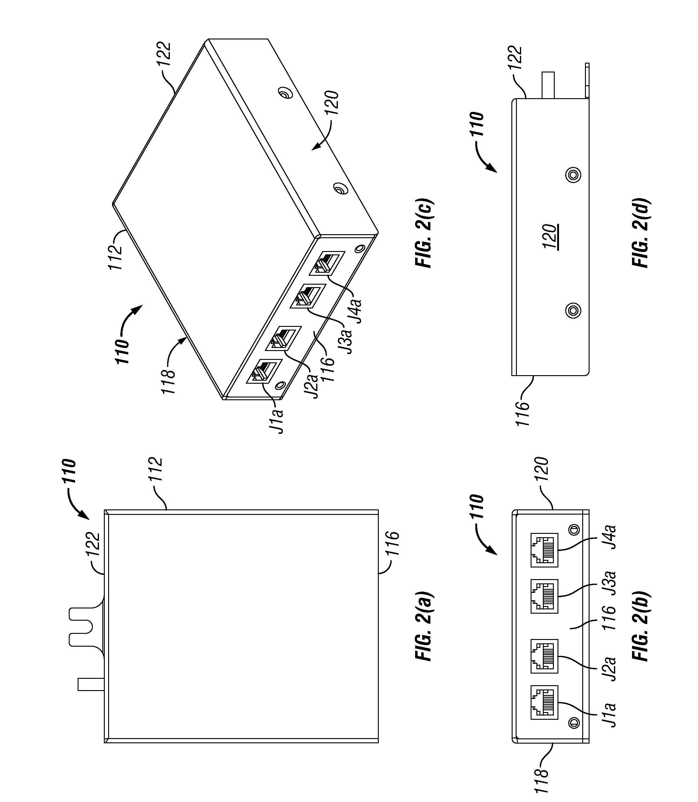
[0036]In FIGS. 2(a)-2(d), there is illustrated an I / O signal protector assembly 110 which is constructed in accordance with the principles of the present invention. The rackmount I / O signal protector assembly 110 includes a substantially rectangularly-shaped housing enclosure 112 and has a front wall member 116, opposed side wall members 118 and 120, and a rear wall member 122. A pair of gigabit input or exposed side connector devices J1a and J3a are mounted in the front wall member 116 of the housing enclosure 112 and are adapted to receive various incoming telecommunication lines carrying the different input voice or data signals.
[0037]A pair of gigabit output or protected side connector devices J2a and J4a are also mounted in the front wall member 116 of the housing enclosure 112 and are adapted for connection to various sensitive consumers' equipment to be protected. It will be noted again that each of the output side connector devices J2a and J4a are mounted adjacent to the cor...
third embodiment
[0040]In FIGS. 3(a)-3(e), there is illustrated a rackmount I / O signal protector assembly 210 which is constructed in accordance with the principles of the present invention. The rackmount I / O signal protector assembly 210 is substantially identical in its structure to the protector assembly 10. The rackmount I / O signal protector assembly 210 includes a substantially rectangularly-shaped housing enclosure 212 and has a front wall member 216, opposed side wall members 218 and 220, and a rear wall member 222. A pair of gigabit input or exposed side connector devices J1b and J3b are mounted in the front wall member 216 adjacent to the right end of the housing enclosure 212 and are adapted to receive various incoming telecommunication lines carrying the different input voice or data signals. A pair of gigabit output or protected side connector devices J2b and J4b are also mounted in the front wall member 216 adjacent to the right end of the housing enclosure 212 and are adapted for conne...
fourth embodiment
[0044]In FIGS. 4(a)-4(e), there is illustrated a rackmount I / O signal protector assembly 310 which is constructed in accordance with the principles of the present invention. The rackmount I / O signal protector assembly 310 is substantially identical in its structure to the protector assembly 210. The rackmount I / O signal protector assembly 310 includes a substantially rectangularly-shaped housing enclosure 312 and has a front wall member 316, opposed side wall members 318 and 320, and a rear wall member 322.
[0045]In the front wall member 316 adjacent to the right end of the housing enclosure 312, there is mounted the same gigabit input / output side connector devices J1b, J2b, J3b and J4b as shown in FIG. 3(a)-3(e). Also, in the front wall member 316 adjacent to the left end of the housing enclosure 312, there is mounted the same alarm input / output side connector devices J16 through J19 as shown in FIG. 3(a)-3(e).
[0046]In addition, in the middle section of the front wall member 316 the...
PUM
 Abstract
Description
Claims
Application Information
 - R&D
- Intellectual Property
- Life Sciences
- Materials
- Tech Scout
- Unparalleled Data Quality
- Higher Quality Content
- 60% Fewer Hallucinations
Browse by: Latest US Patents, China's latest patents, Technical Efficacy Thesaurus, Application Domain, Technology Topic, Popular Technical Reports.
© 2025 PatSnap. All rights reserved.Legal|Privacy policy|Modern Slavery Act Transparency Statement|Sitemap|About US| Contact US: help@patsnap.com


