Height-adjustable implant to be inserted between vertebral bodies and corresponding handling tool

a technology of adjusting device and insertion device, which is applied in bone implants, prostheses, medical science, etc., can solve the problem that the nut is not otherwise secured on the first sleeve part, and achieve the effect of less material, less weight, and preventing mutual rotation

Active Publication Date: 2013-10-29
KRAUS KILIAN +1
View PDF260 Cites 21 Cited by
  • Summary
  • Abstract
  • Description
  • Claims
  • Application Information

AI Technical Summary

Benefits of technology

[0006]The nut of the implant bears a toothed ring and is therefore designed as a gear. The height of the implant can be adjusted with the aid of a tool incorporating an appropriate complementary element, for example a driving gear, in which case there is no need to perform any pivoting movements with the manipulating tool. Furthermore, the tool does not have to be repositioned several times. Instead, it can be held in one and the same position during the entire process of making the height adjustment, which significantly simplifies the operation and reduces the time needed for the operation.
[0009]In a particularly preferred example of an embodiment of the invention, the two sleeve parts have axially extending windows opening in their mutually facing ends, in which case the peripheral portions disposed between two adjacent windows lie so as to be axially displaceable in the windows of the other respective sleeve part. The advantage of this compared with an arrangement in which the two sleeve parts engage concentrically one inside the other is that less material is necessary and the implant is therefore more lightweight overall. Furthermore, a significantly larger interior is available, which can be filled with bone material or similar. Due to the fact that the two sleeve parts mesh with one another like a comb, they are ultimately guaranteed to be fixedly secured, preventing mutual rotation.
[0010]A radially widened end plate is provided as a means of supporting the implant on a vertebral body. In a preferred embodiment, this is a separate, releasably fixed part. The appropriate end plate, for example one with a flat plane extending at an angle to the mid-longitudinal axis of the implant, may be used in each individual case. If the end plate is secured on the sleeve part by means of a snap-fit connection, a secure mount on the sleeve part can be guaranteed on the one hand, whilst making replacement easy on the other hand. In one embodiment which is simple from the point of view of production and assembly, an annular groove is provided in the internal wall of the sleeve part close to the end face, in which catch lugs integrally moulded on the underside of the end plate locate.
[0011]A manipulating tool for the implant described above has a gear co-operating with the nut. A retaining mechanism is preferably provided on the manipulating tool as a means of holding the implant immobile. The gear is disposed so that its axis extends transversely to the axis of the toothed ring of the nut during the driving operation. As mentioned above, a deflection of the rotating movement of the drive axis is not necessary. In one arrangement that is particularly compact and easy to operate, the toothed ring is disposed on the end face of a tubular portion and the tubular portion has a rod extending through it, the free end of which projects out from the tubular portion and can be screwed into the threaded bore of the first sleeve part. The coaxial disposition of the tubular portion and the rod results in a compact manipulating tool that is easy to operate.

Problems solved by technology

However, the nut is not otherwise secured on the first sleeve part.

Method used


Image

  • Height-adjustable implant to be inserted between vertebral bodies and corresponding handling tool
  • Height-adjustable implant to be inserted between vertebral bodies and corresponding handling tool
  • Height-adjustable implant to be inserted between vertebral bodies and corresponding handling tool

Examples


Embodiment Construction

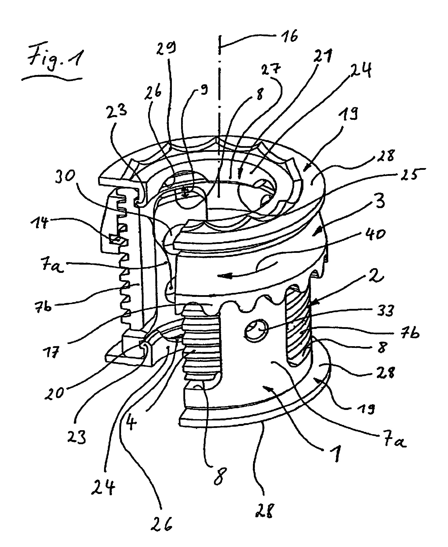
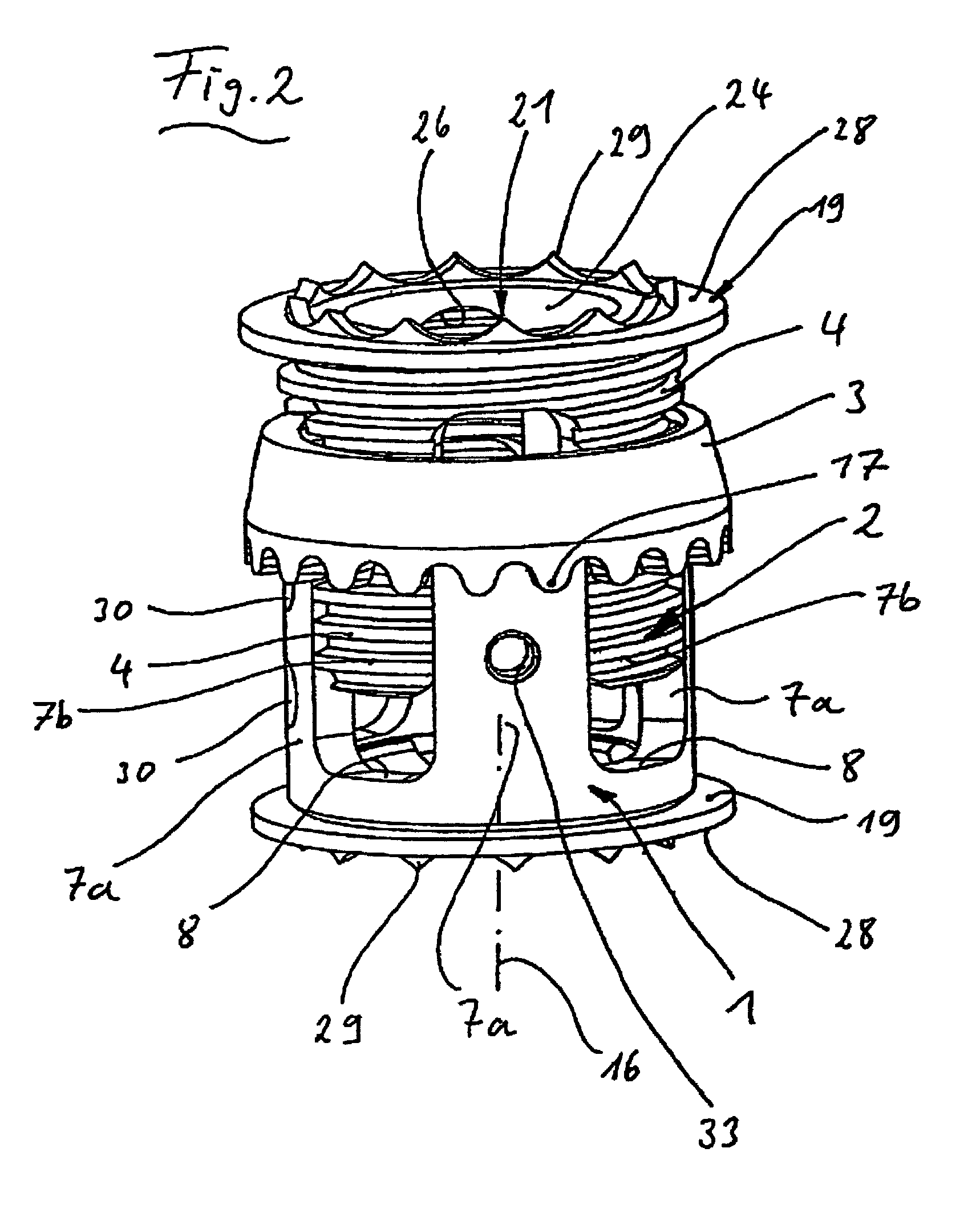
[0020]The implant illustrated in the drawings comprises a first sleeve part 1, a second sleeve part 2 and a nut 3 as its main components. The sleeve part 2 is provided with an external thread 4 extending essentially across its entire length. Both sleeve parts 1, 2 have axially extending windows 6 which open into their mutually facing end face 5a, b in the assembled state. The peripheral portions 7a, b left between two adjacent windows lie so as to be axially displaceable in the windows 6 of the other respective sleeve part 1, 2. This being the case, the clearance between the peripheral portions 7a, b is dimensioned so as to guarantee that the two sleeve parts will sit without wobbling but easily slide one inside the other. The sleeve parts 1, 2 have a more or less identical wall thickness and the same internal diameter, i.e. the peripheral portions 7b of the second sleeve part 2 do not project beyond the external circumference or beyond the internal circumference of the sleeve part ...


PUM


Abstract

A height-adjustable implant is designed to be inserted between vertebral bodies and includes a first and a second sleeve part. The second sleeve part carries an external thread and is inserted with a longitudinal section thereof in the first sleeve part in a rotationally fixed and axially movable manner. On its longitudinal section projecting from the first sleeve part, the second sleeve part is encompassed by a nut that engages with the external thread. The nut carries a toothed ring. The invention also relates to a tool for handling the implant.

Description

BACKGROUND OF THE INVENTION[0001]1. Field of the Invention[0002]The invention relates to a height-adjustable implant for insertion between vertebral bodies and a tool suitable for the manipulation thereof.[0003]2. Present State of the Art[0004]An implant known from patent specification DE 196 22 827 A1, for example, has a first and a second sleeve part, which second sleeve part has an external thread which is placed in the first sleeve part by means of a longitudinal portion so as to be prevented from rotating and axially displaceable whilst its longitudinal portion projecting out from the first sleeve part is enclosed by a nut engaging in the external thread. When the nut is rotated, the second sleeve part is moved out of the first sleeve part. In order to operate the nut, a rod-shaped manipulating tool is inserted by its free end in a recess on the external circumference of the nut. By pivoting the tool in a plane extending transversely to the longitudinal axis of the implant, the...

Claims


Application Information

Patent Timeline
Patent Type & Authority Patents(United States)
IPC IPC(8): A61F2/44A61B17/88A61F2/46A61F2/00A61F2/28A61F2/30
CPCA61F2/4611A61F2/44A61F2/30744Y10T74/19585A61F2/442A61F2002/2835A61F2002/302A61F2002/30331A61F2002/30392A61F2002/30405A61F2002/305A61F2002/30507A61F2002/30512A61F2002/30523A61F2002/3055A61F2002/30601A61F2002/30772A61F2002/30841A61F2002/3085A61F2002/4475A61F2002/4627A61F2002/4629A61F2220/0025A61F2220/0033A61F2230/0065A61F2002/30593
Inventor KRAUS, KILIANSAAL, NORBERT
Owner KRAUS KILIAN
Why Eureka
Try Eureka