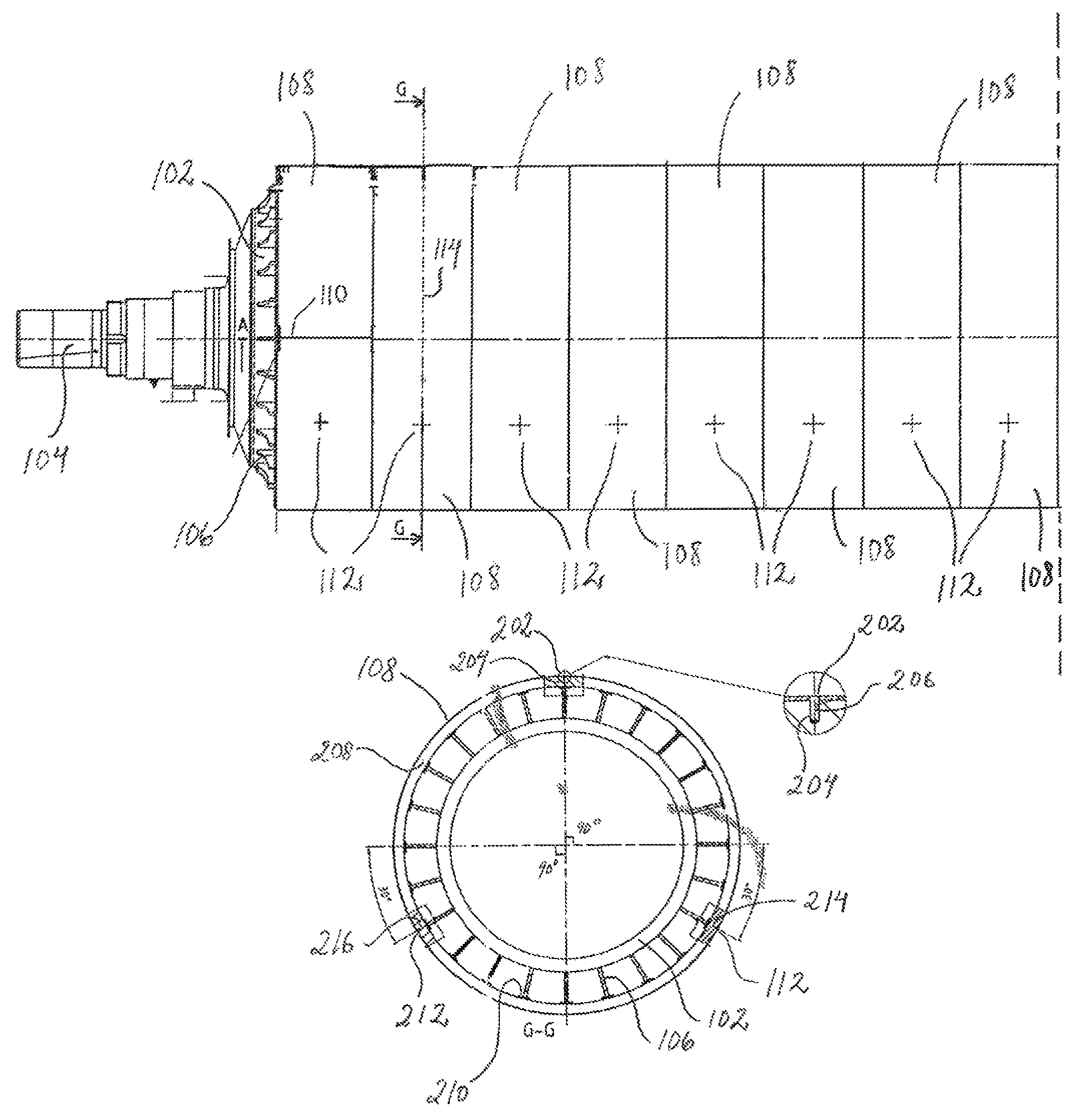
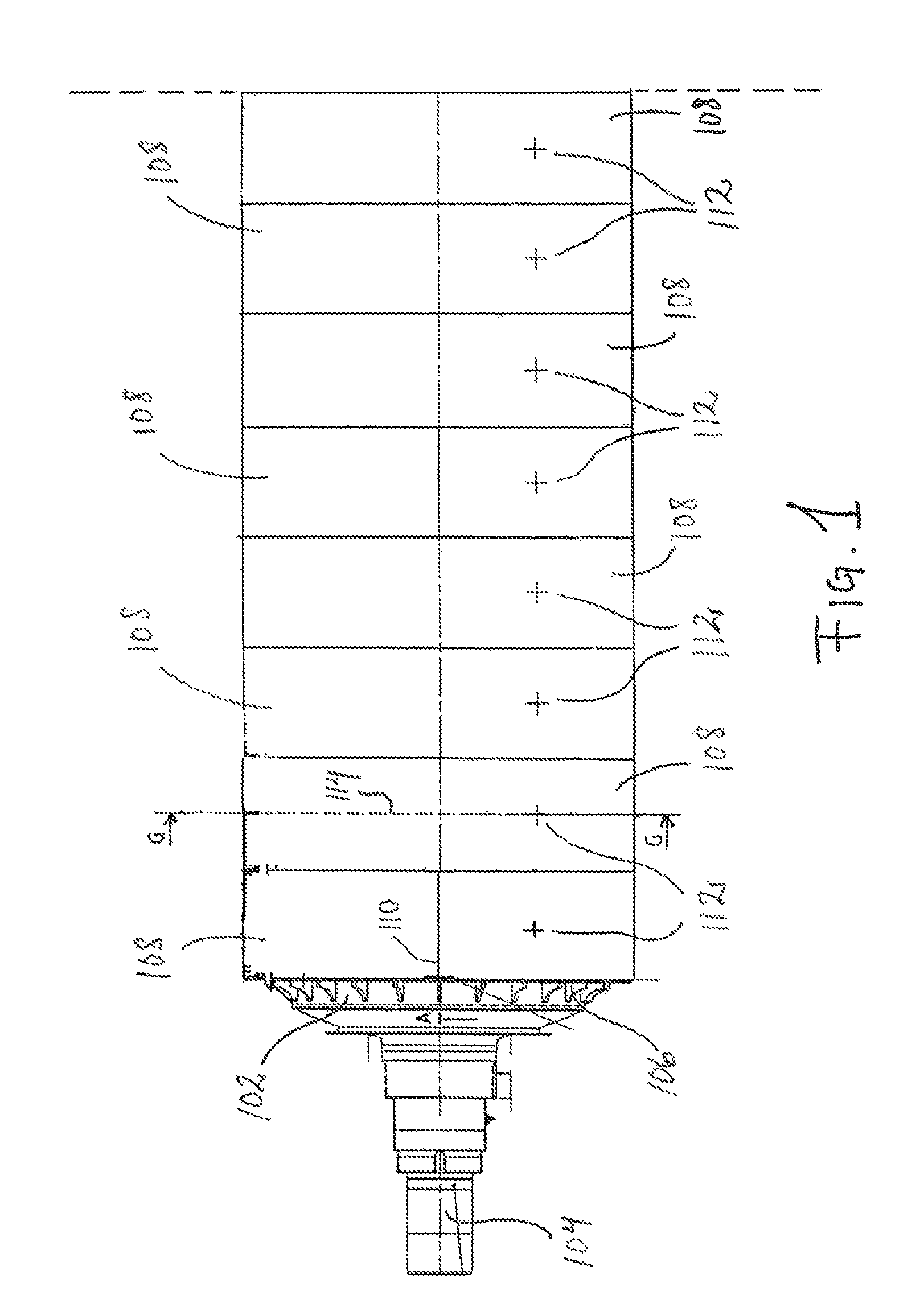
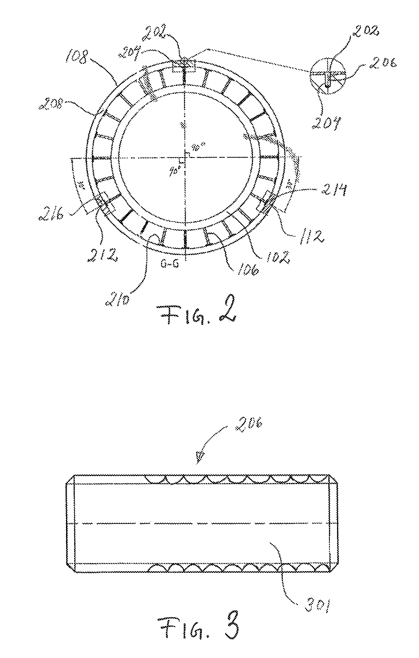
[0010]In accordance with the present invention, this and other objects have now been realized by the invention of a press roll for washing or dewatering pulp comprising an axially-extending core, a mantle section attached around the axially-extending core, at least one perforated roll plate attached to the mantle section and extending around the entire circumference of the press roll so that the at least one perforated roll plate includes a pair of circumferentially-extending edges and a pair of end edges, the at least one perforated roll plate comprising a plurality of mounting openings disposed between the pair of end edges and distributed around the entire circumference of the press roll, and a plurality of fixing pins corresponding to the plurality of mounting openings, each of the plurality of fixing pins being anchored to the mantle section and being surrounded by the corresponding plurality of mounting openings, whereby movement of the at least one perforated roll plate relative to the mantle section in a circumferential direction of the press roll is prevented. In a preferred embodiment, the plurality of mounting openings are centrally disposed between the pair of circumferentially-extending edges of the at least one perforated roll plate. In a preferred embodiment, the plurality of mounting openings are disposed along the longitudinally-extending center line of the at least one perforated roll plate.
[0016]In accordance with the present invention, a method has also been invented for providing a press roll for washing or dewatering pulp, the press roll comprising an axially-extending core, and a mantle section attached around the axially-extending core, the method comprising attaching at least one perforated roll plate to the mantle section so that it extends around the entire circumference of the press roll, whereby the at least one perforated roll plate includes a pair of circumferentially-extending edges and a pair of end edges, drilling a plurality of mounting openings between the pair of end edges and distributed around the entire circumference of the press roll, inserting a plurality of fixing pins into each of the plurality of mounting openings, and anchoring each of the plurality of fixing pins in the mantle section, whereby the plurality of fixing pins are surrounded by the corresponding plurality of mounting openings, and movement of the at least one perforated roll plate relative to the mantle section in the circumferential direction of the press roll is prevented. In a preferred embodiment, attaching of the at least one perforated roll plate comprises providing the at least one perforated roll plate around the mantle section and contracting the at least one perforated roll plate thereabout.
[0018]In accordance with another embodiment of the method of the present invention, drilling of the plurality of mounting openings comprises evenly distributing the plurality of mounting openings around the entire circumference of the press roll, whereby the distance between each adjacent one of the plurality of mounting openings is substantially the same.
[0022]In accordance with the present invention, a press roll is obtained where the risk of cracks in the roll plate is radically reduced, because of the replacement of the welding seams along the long sides of the roll plate by the innovative mounting openings and attachment pins, which provide a locking of the roll plate to the mantle section, i.e. movement of the roll plate in relation to the mantle section in the circumferential direction of the press roll is prevented, without any welding of the long sides of the roll plate. In this manner, stoppage as a result of broken roll plates, which must then be replaced, is prevented. By means of the present invention it is also easier to change worn or damaged roll plates, as the roll plate to be replaced does not need to be released from any welding seams at its long sides. The manufacturing of the press roll is also facilitated, because subsequent grinding of the weld reinforcement, as a result of the welding of the long sides of the roll plate, is not needed. The present invention is especially advantageous for press rolls where the roll plate extends around the entire circumference of the press roll.
[0023]According to an advantageous embodiment of the present invention, the roll plate is provided with at least three mounting openings, into which fixing pins are received. For larger press rolls, it is advantageous with six mounting openings into which fixing pins are received, but other numbers of mounting openings are possible. Advantageously, the mounting openings are evenly distributed around the entire circumference of the press roll so that the distance between two mounting openings, which are adjacent to each other in the circumferential direction of the press roll, is substantially equal around the entire circumference of the press roll. In the case of three mounting openings, two mounting openings, which are adjacent to each other in the circumferential direction of the press roll, are spaced apart by about 120° in the cross section of the roll press, and in the case of six mounting openings, two mounting openings, which are adjacent to each other in the circumferential direction of the press roll, are spaced apart by about 60° in the cross section of the roll press. The fact that the distances between the mounting openings are equal facilitates drilling of the holes.
[0024]According to a further advantageous embodiment of the present invention, the mounting openings are centrally positioned between the long sides of the roll plate, and advantageously along the longitudinal center line of the roll plate. In this manner, symmetry in the structure is provided, which is advantageous. Alternatively, three mounting openings can for example be provided along the first long side of the roll plate and three additional mounting openings can be provided along the second long side of the roll plate, opposite the mounting openings at the first long side, whereby the desired symmetry in the structure is also obtained.