
Mechanical insufflation/exsufflation airway clearance apparatus

a technology of airway clearance and mechanical insufflation, which is applied in the field of mechanical insufflation/exsufflation airway clearance apparatus, can solve the problems of no real improvement in mei functionality in 50 years, size and weight, and serious limitations of current machines, and achieve the effect of maximizing airflow

Active Publication Date: 2013-09-24
HILL ROM SERVICES
View PDF44 Cites 45 Cited by
  • Summary
  • Abstract
  • Description
  • Claims
  • Application Information

AI Technical Summary

Benefits of technology

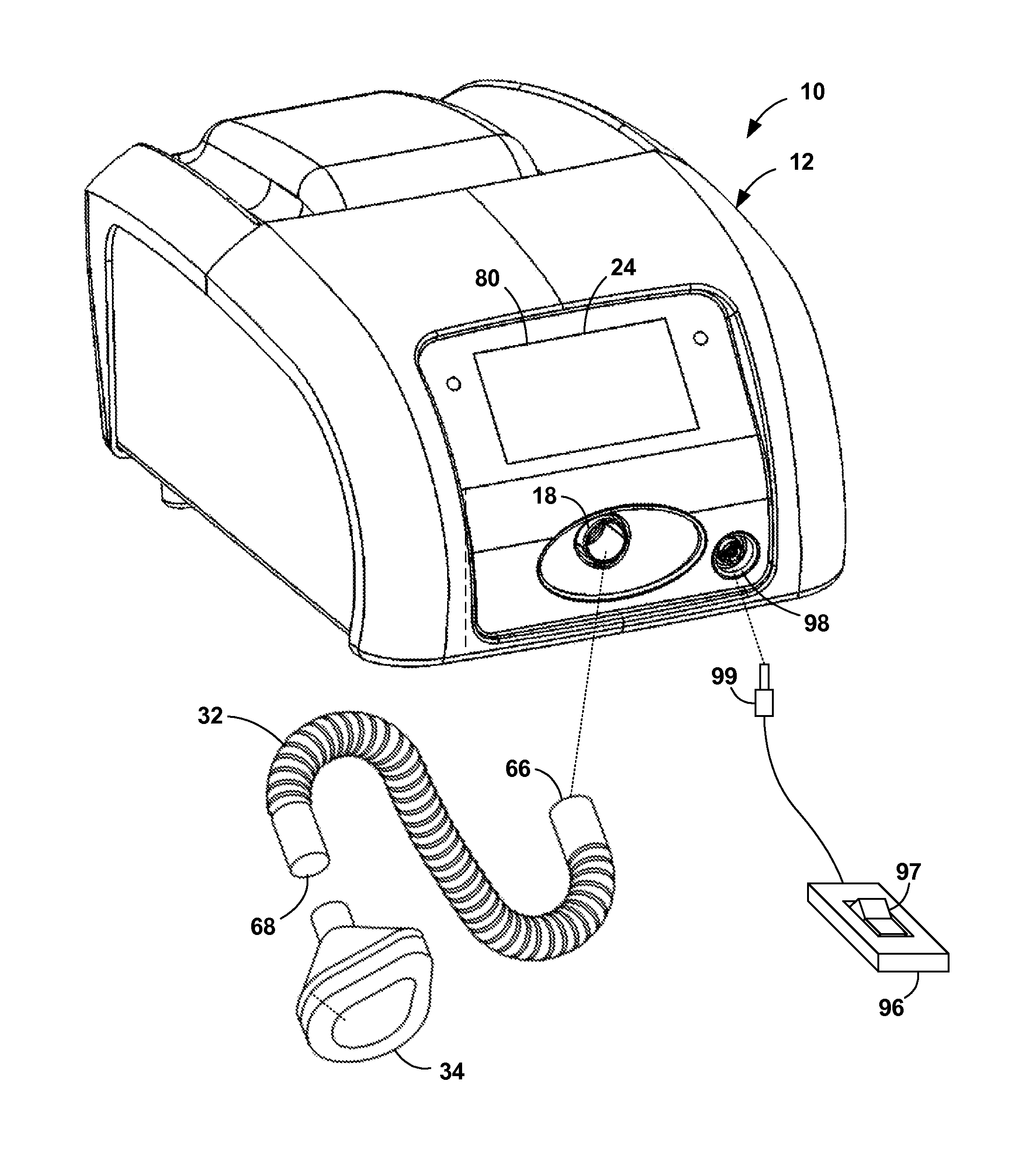
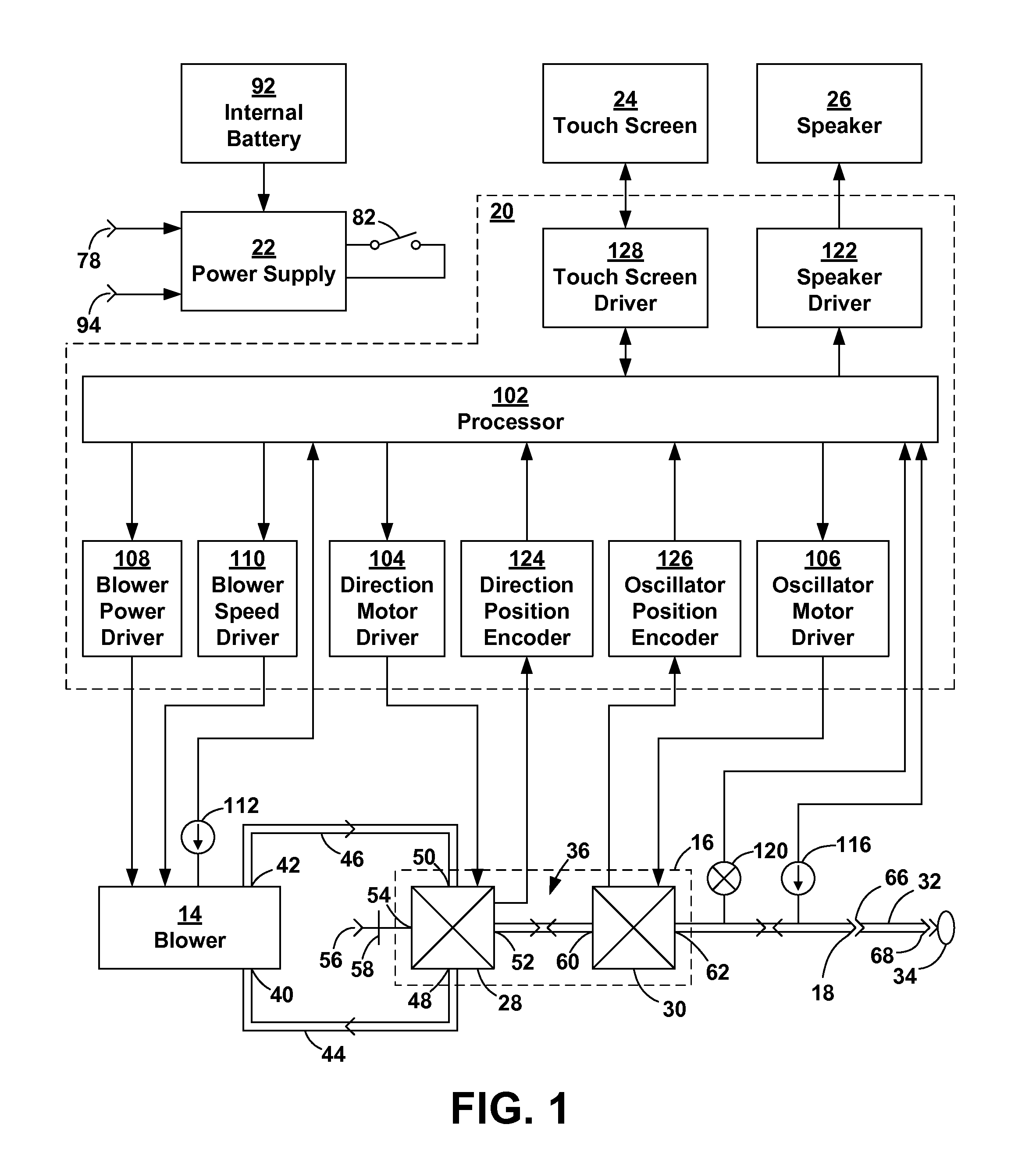
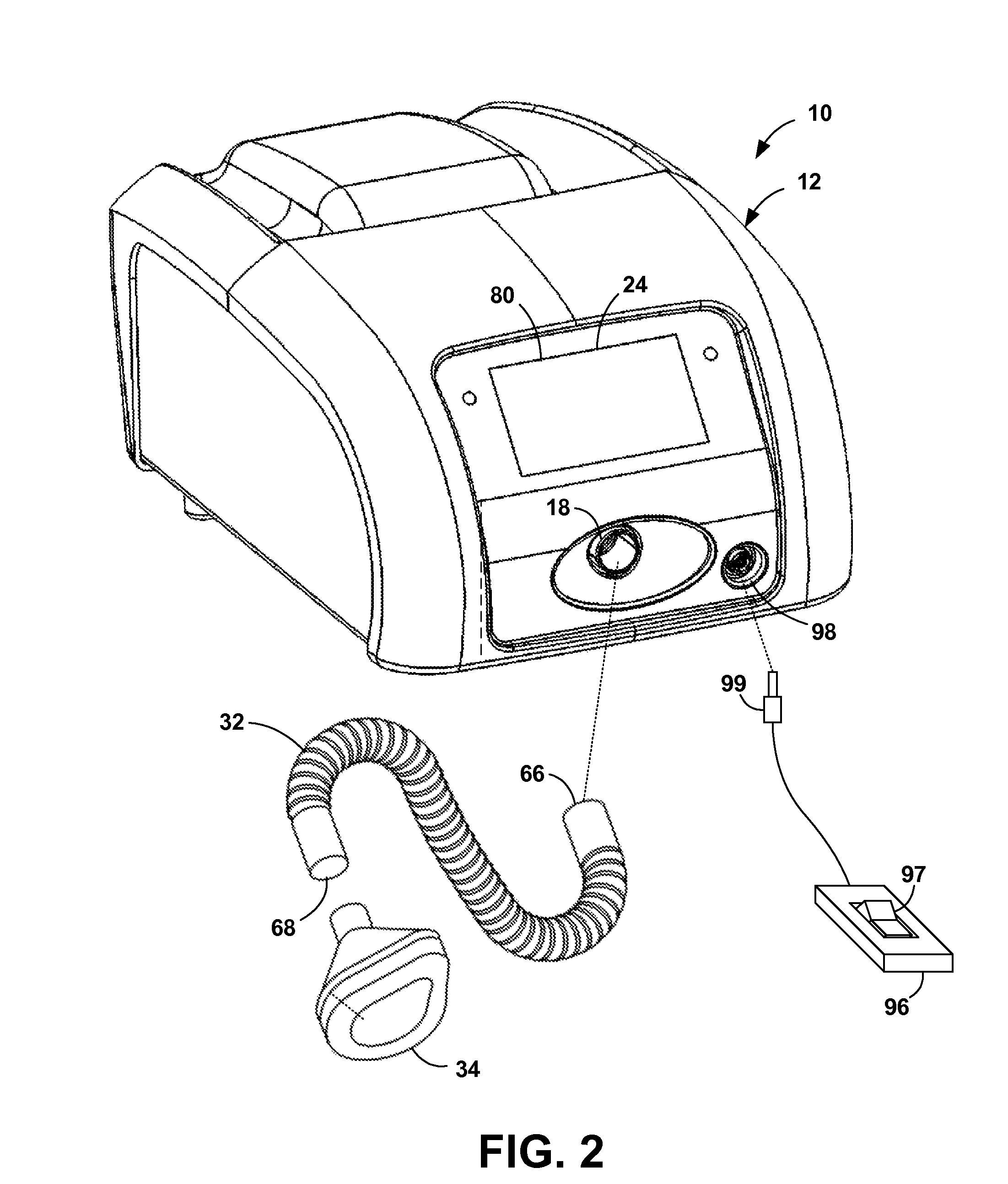
The MIE apparatus is a medical device that helps patients with breathing problems. It has a case with a blower, valve subassembly, hose connector, controller, power supply, and touch screen. The apparatus has two modes: insufflation and exsufflation. The blower intake and exhaust are connected to the valve subassembly, which also has a direction valve and an oscillator. The direction valve connects to the valve port of the oscillator or the mask hose connector. The apparatus can be used manually or automatically, with different parameters for insufflation and exsufflation. The patient touches a button to turn the blower on or off. In automatic mode, the apparatus cycles through insufflation and exsufflation until the set number of cycles is reached. Overall, the MIE apparatus provides a safe and effective therapy for patients with breathing problems.

Problems solved by technology

Professionals using mechanical Insufflators / Exsufflators (MIEs) have realized over the years that there are serious limitations to current machines.
There have been no real improvement in MEI functionality in 50 years.
Size and weight are a problem.
In order to operate in many vehicles with a 12 volt DC system, inverters have to be installed, which are expensive and complicated to install.
For many patients with thick secretions, current MIEs need a great amount of time and additional intervention to mobilize and remove them.

Method used


Image

  • Mechanical insufflation/exsufflation airway clearance apparatus
  • Mechanical insufflation/exsufflation airway clearance apparatus
  • Mechanical insufflation/exsufflation airway clearance apparatus

Examples


Embodiment Construction

[0034]The present invention is an apparatus for assisting in coughing. One feature of the present invention is the ability to vibrate the airway. Vibration of the airway at a specific frequency creates the phenomenon known as “enhanced diffusivity”. This mechanism changes the rate of diffusion in the alveolar-capillary membrane of the lung. By changing the diffusion coefficient in the lung, greater amounts of oxygen can be put into the blood stream and greater amounts of carbon dioxide can be removed. The special valve that creates this function is a rotating butterfly-type mechanism which has an adjustable frequency for conforming to specific pulmonary physiologies.

[0035]Another feature is the ability to use the apparatus to recruit lung volume. The apparatus uses a mechanism to gradually adjust the base pressure at the end of exsufflation. This creates a degree of positive pressure inside the lung thereby helping the lung to reinflate when vital capacity has been decreased due to ...


PUM


Abstract

An MIE apparatus has a blower, a direction valve, an oscillator, and a mask hose connector. The blower is connected to the direction valve, which is connected to the oscillator, which is connected to the hose connector. During insufflation, a direction valve connects exhaust of a blower to an oscillator, causing positive pressure at the hose connector. During exsufflation, the direction valve connects the blower intake to the oscillator, causing negative pressure at the hose connector. The oscillator is a butterfly valve with a 360° rotating disc. During insufflation, the disc is fixed to steadily modulate the airflow. During exsufflation, the oscillator is inactive or in flutter mode. When inactive, the disc is fixed to allow maximum air flow. In flutter mode, the disc continuously rotates so that the air flow rapidly alternates between maximum and minimum.

Description

CROSS-REFERENCES TO RELATED APPLICATIONS[0001]Not ApplicableSTATEMENT REGARDING FEDERALLY SPONSORED RESEARCH OR DEVELOPMENT[0002]Not ApplicableREFERENCE TO A SEQUENCE LISTING, A TABLE, OR A COMPUTER PROGRAM LISTING COMPACT DISK APPENDIX[0003]Not ApplicableBACKGROUND OF THE INVENTION[0004]1. Field of the Invention[0005]The present invention relates to medical devices, more particularly, to devices that aid in breathing and in inducing coughs.[0006]2. Description of the Related Art[0007]Professionals using mechanical Insufflators / Exsufflators (MIEs) have realized over the years that there are serious limitations to current machines. There have been no real improvement in MEI functionality in 50 years.[0008]Parents of pediatric patients, as well as many adult patients, take the machine everywhere with them. Size and weight are a problem.[0009]MEIs typically operated on 120 volts AC. In order to operate in many vehicles with a 12 volt DC system, inverters have to be installed, which are...

Claims


Application Information

Patent Timeline
Patent Type & Authority Patents(United States)
IPC IPC(8): A61M11/00
CPCA61M16/20A61M16/06A61M16/00A61M16/202A61M16/0006A61M16/0066A61M2205/3368A61M2205/505A61M2016/0027A61M16/0009A61M16/0069A61M16/107A61M16/205A61M16/024A61M16/0816A61M2205/3331A61M2205/502A61M2209/06A61M16/0003A61M16/204
Inventor CARBONE, DANO S.IKEI, CHRISTOPHERWARD, LEWIS W.STULTZ, TAMMY
Owner HILL ROM SERVICES
Learn More