
Integrated material transfer and dispensing system

a material transfer and dispensing system technology, applied in liquid transferring devices, volume meters, instruments, etc., can solve the problems of damage to pumping equipment, prior known material management systems have encountered difficulties in transferring from containment vessels, etc., and achieve greater operational temperature range and high fluid flow rate

Active Publication Date: 2013-09-17
CH & I TECH INC
View PDF68 Cites 17 Cited by
  • Summary
  • Abstract
  • Description
  • Claims
  • Application Information

AI Technical Summary

Benefits of technology

The present invention is about a system for transferring different materials, such as thick fluids, that can be difficult to pump. The system is designed to be refillable and can dispense materials without the need for a separate pump. It also provides information to users about how much fluid is left in the container. The system can deliver high fluid flow rates and is adaptable to different temperatures. The invention includes a vessel with a force transfer device and an annulus management device that can be attached to the vessel. The system can also have various sensors and communication devices connected to them for monitoring and controlling the transfer process. Overall, the invention allows for efficient and safe transfer of materials without the need for a separate pump.

Problems solved by technology

Prior known material management systems have encountered difficulty transferring from a containment vessel certain thick, viscous fluids, liquids and other types of materials that may resist pumping and that can be damaging to pumping apparatus.
Various components of fluid delivery systems are known, but are typically configured with heavy-duty pumps and are not integrated with a material delivery system having process controls and / or a computer interface capability.

Method used


Image

  • Integrated material transfer and dispensing system
  • Integrated material transfer and dispensing system
  • Integrated material transfer and dispensing system

Examples


Embodiment Construction

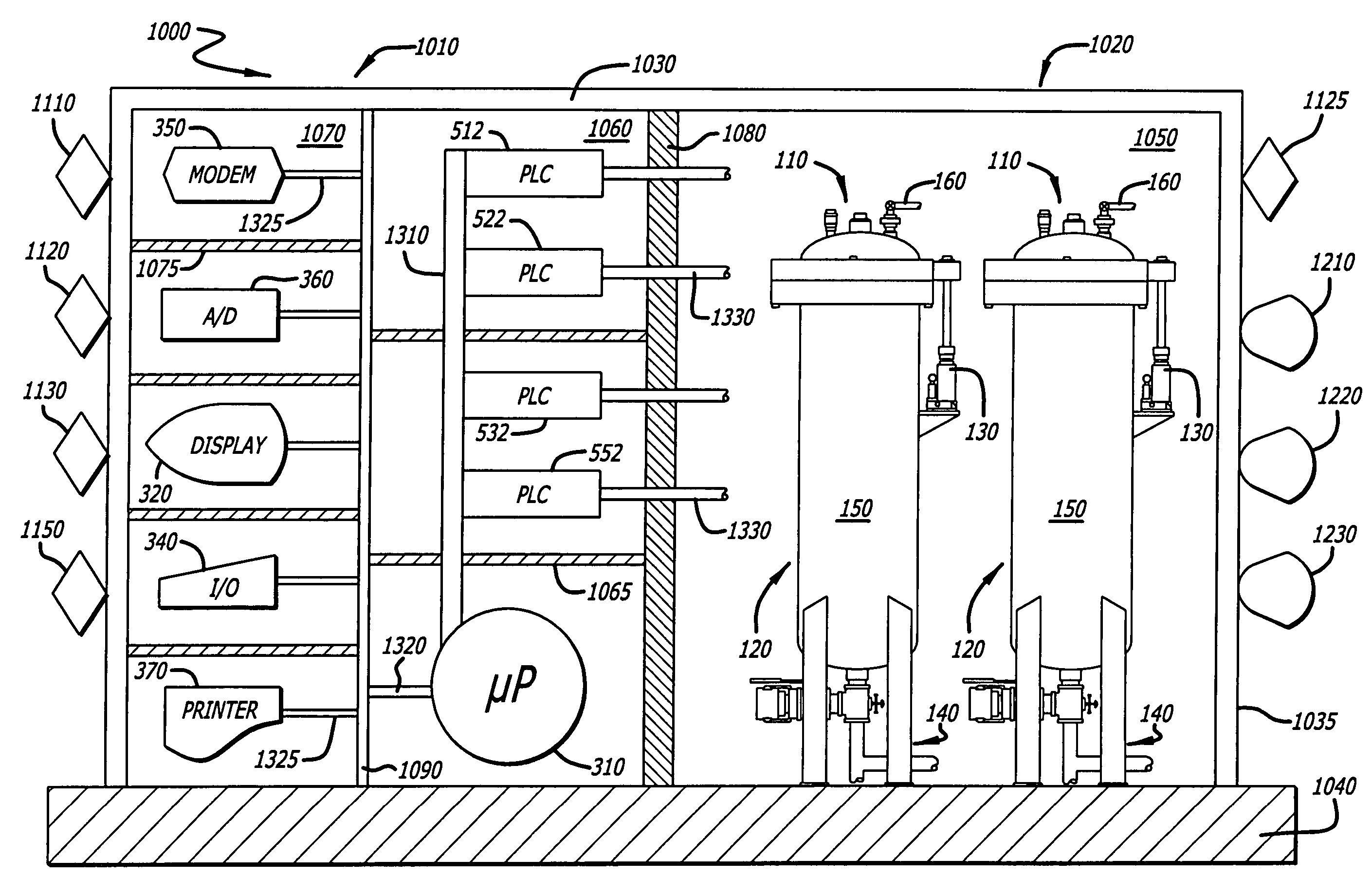
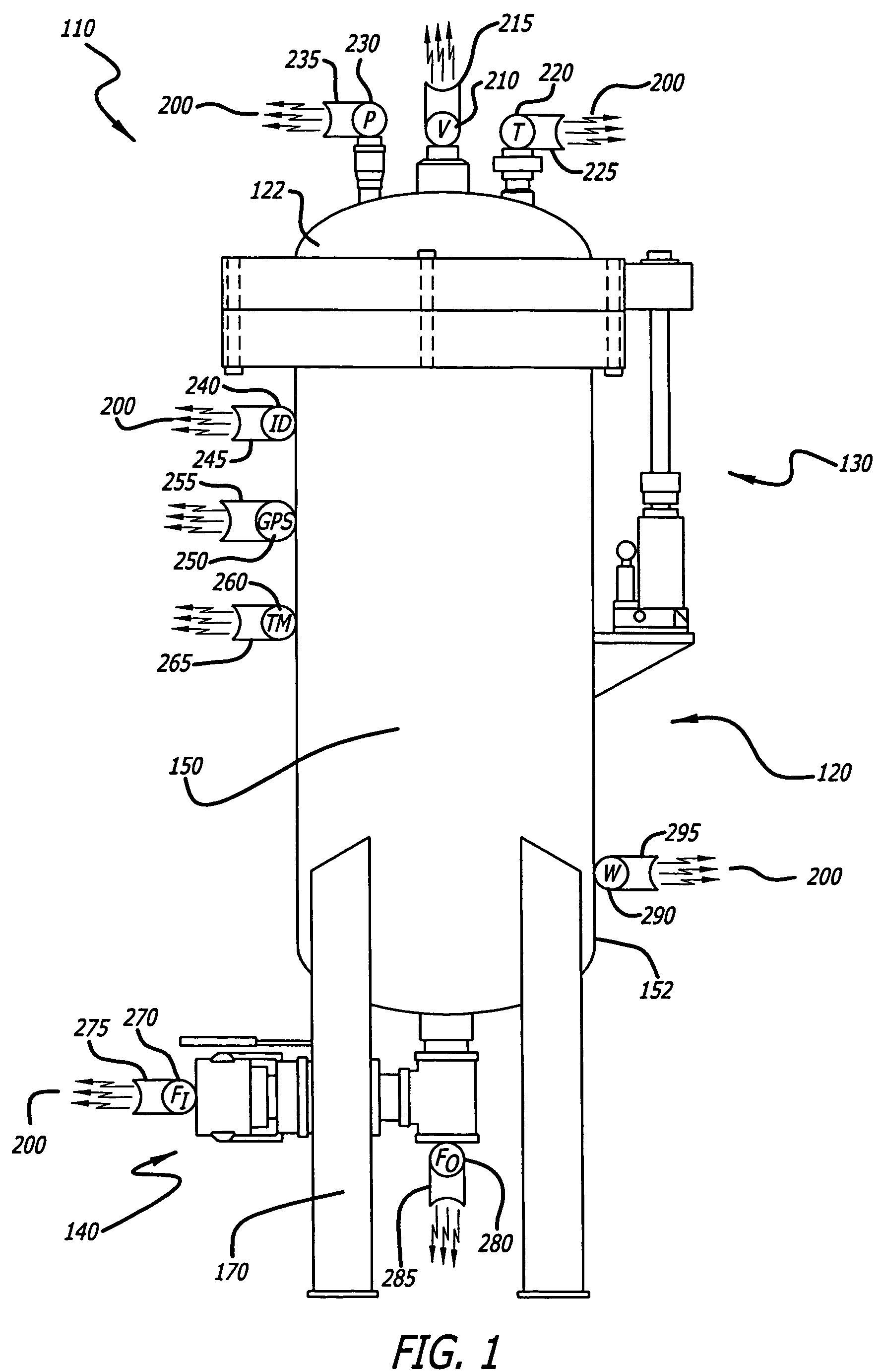
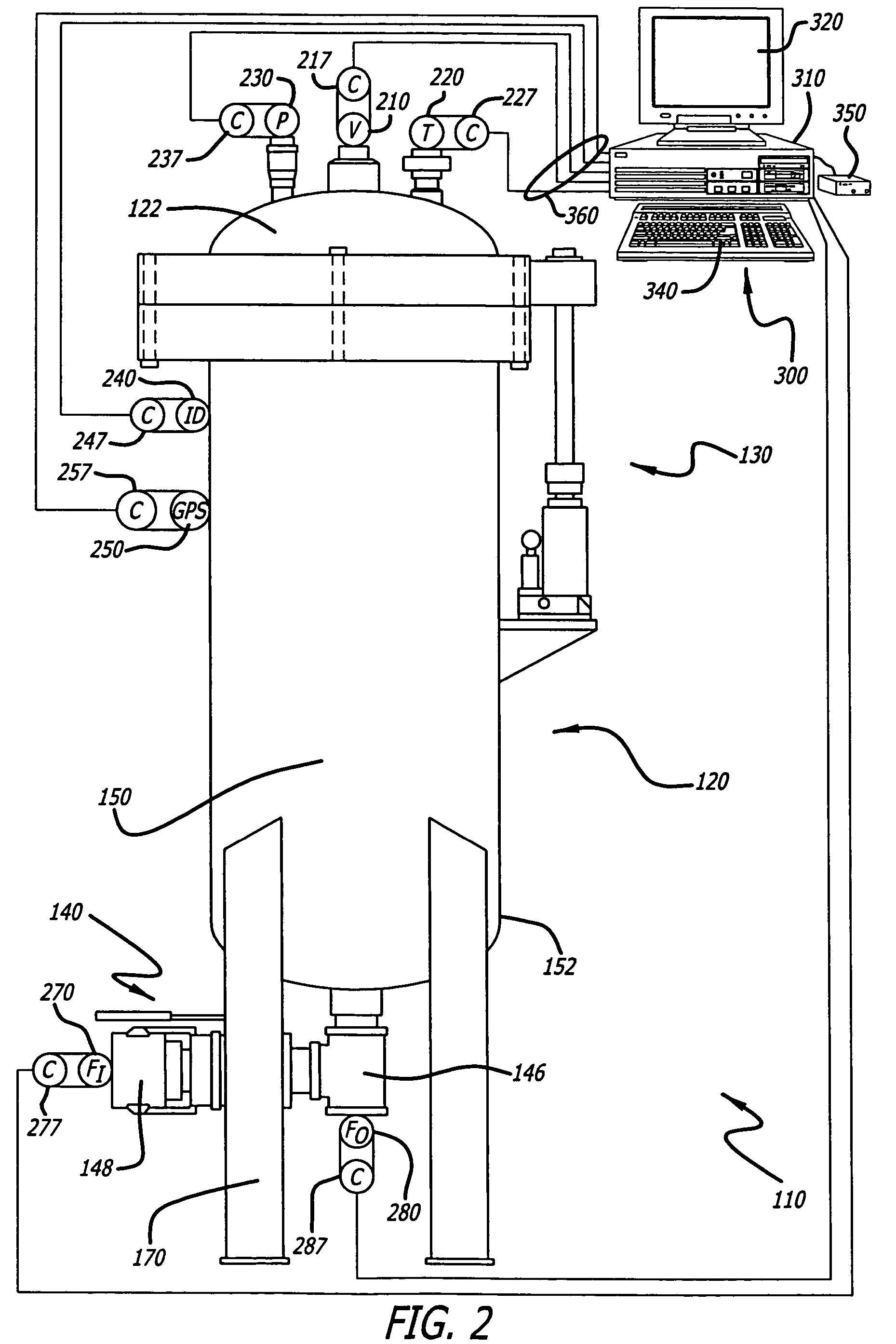
[0035]As shown in the drawings for purposes of illustration, the present invention is directed to integrated material transfer and dispensing systems for dispensing various materials, including, but not limited to, oils, greases, mastics, sealants, elastomers and other types of fluids, such as liquid applied sound deadener (LASD). The system includes a material containment vessel with an upper region incorporating a motive force, and a bottom region with a material ingress and egress opening. A diconical or other shaped, level-instrumented force transfer device may be located in the material containment area. The present invention further includes incorporating a data acquisition system into known and yet to be developed refillable material transfer system technology.

[0036]Turning now to the drawings, in which like reference numerals represent like or corresponding aspects of the drawings, and with particular reference to FIG. 1, one embodiment of the intelligent automated material ...


PUM


Abstract

An integrated material transfer and dispensing system for storing, transferring and dispensing materials, such as fluids, and liquids, for example, liquid applied sound deadener (LASD). The system includes at least one vessel having a force transfer device. Each vessel may be removably enclosed in cabinet to form an automated station. Each vessel may be configured with a data logger, cleanout port, a sample valve at least one sight window and an access port for introducing a compound such as a biocide. Each vessel may be configured with instruments including sensors for measuring process variables, such as material volume, level, temperature, pressure and flow. The system may further include a metering device system and a robotic material dispenser system without a pump interface. The robotic system may further include a computer control system connected to flow and pressure sensors. The system may directly feed an applicator without an intervening pump.

Description

CROSS-REFERENCE TO RELATED APPLICATIONS[0001]This application claims the benefit of U.S. Provisional Patent Application Ser. No. 60 / 729,321, filed Oct. 21, 2005; U.S. Provisional Patent Application Ser. No. 60 / 729,405, filed Oct. 21, 2005; U.S. Provisional Patent Application Ser. No. 60 / 757,360, filed Jan. 9, 2006; and U.S. Provisional Patent Application Ser. No. 60 / 841,111, filed Aug. 29, 2006, the contents of which are each hereby incorporated herein by reference. The contents of U.S. Provisional Patent Application Ser. No. 60 / 558,691, filed Mar. 31, 2004; U.S. Non-Provisional patent application Ser. No. 11 / 096,356, filed Mar. 31, 2005 (now U.S. Publication No. 2005 / 0232,072); and U.S. Pat. No. 5,435,468 are each hereby incorporated herein by reference.BACKGROUND OF THE INVENTION[0002]The present invention relates to the field of materials management, and more particularly to systems designed for containing, transferring, delivering and dispensing various materials, such as liquid...

Claims


Application Information

Patent Timeline
Patent Type & Authority Patents(United States)
IPC IPC(8): B67D1/00B65D83/00B67D7/60B67D7/02
CPCB65D83/0005B67D7/0233B67D2210/0016B67D2210/0006
Inventor WILLIAMS, ERIC A.LEVENSTEIN, LAWRENCE M.THIBODEAU, ROBERT D.
Owner CH & I TECH INC
Learn More