
Transmission method for uplink transport layer

a technology of transmission method and transport layer, applied in the field of uplink data packet transmission, can solve the problem of limited overall network capacity, and achieve the effect of reducing congestion at the transport layer

Inactive Publication Date: 2013-09-10
NEC CORP
View PDF19 Cites 5 Cited by
  • Summary
  • Abstract
  • Description
  • Claims
  • Application Information

AI Technical Summary

Benefits of technology

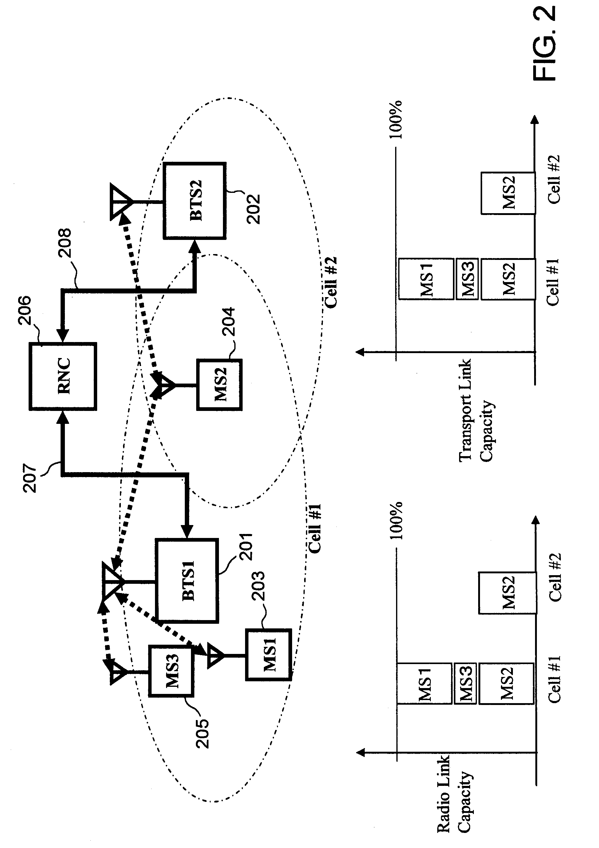
[0012]An illustration of aforementioned problem is given in FIG. 2. In this example, two base stations (BTS1, BTS2) 201, 202 are serving three mobile stations (MS1, MS2, MS3) 203, 204, 205 which transmit data in uplink. Radio network controller (RNC) 206 is controlling both base stations 201, 202 and mobile stations 203, 204, 205. Base station (BTS1) 201 manages cell #1 and base station (BTS2) manages cell #2. Both cells are partially overlapped to each other. Base station (BTS1) 201 is receiving data packets from three mobile stations while the base station (BTS2) 202 is receiving data packets from only mobile station (MS2) 204. Compared to mobile station MS1 and mobile station MS3, the mobile station MS2 is located in a soft handover region between the base stations hence reliability of data packet transmission from mobile station MS2 improved by diversity handover reception. Radio network controller (RNC) 206 receives all data packets transmitted by all mobile stations. More specifically, the packets from mobile station MS2 received by both base stations has to be combined at the radio network controller before delivery to the upper layer.
[0013]From this example, transport link 207 between base station BTS1 and radio network controller 206 suffers heavy traffic due to larger number of serving mobile stations. In fact, all three mobile stations in this example can be connected to both base stations hence increasing the radio layer diversity handover gain. Then transport layer 208 between base station BTS2 and radio network controller 206 will also suffer from the increased traffic to support the radio layer diversity handover gain. Without loss of generality, increasing radio layer diversity handover gain will incur higher bandwidth requirement for a transport layer.
[0014]The object of the present invention is to provide a method of reducing traffic congestion in a transport layer while maximizing radio layer diversity handover gain.Means for Solving the Problem
[0020]According to the present invention, the transport layer congestion can be reduced while maintaining the diversity handover gain at radio layer.

Problems solved by technology

Therefore, the overall network capacity is limited by both radio layer capacity and network layer capacity.

Method used


Image

  • Transmission method for uplink transport layer
  • Transmission method for uplink transport layer
  • Transmission method for uplink transport layer

Examples


first embodiment

[0051]

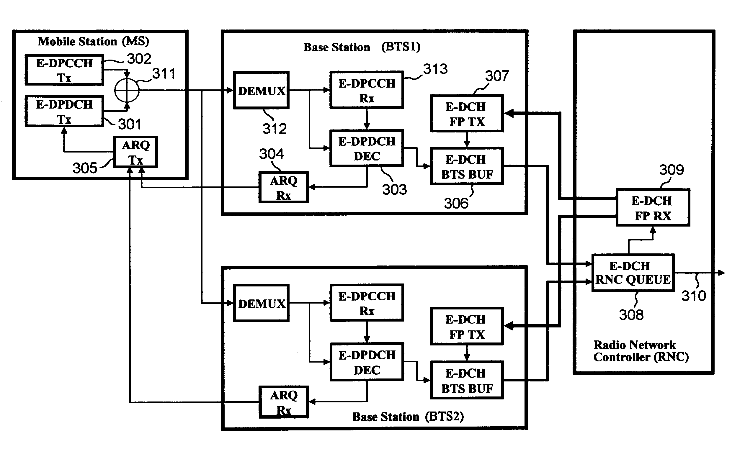
[0052]FIG. 3 illustrates a system according to the first embodiment. The system is provided with a mobile station (MS) connected to two base stations (BTS1, BTS2) while a radio network controller (RNC) is connected to the base stations. This system diagram is also applicable for the case when a mobile station is connected to more than two base stations. More general speaking, a set of base stations in a network is defined as connected set of base stations for a given mobile station. Furthermore, each mobile station in the network may have a different connected set of base stations. Although one mobile station is illustrated in FIG. 3, the network may have a plurality of mobile stations.

[0053]The mobile station (MS) has uplink data transmission unit (E-DPDCH Tx) 301 for transmitting a data packet to the base station, uplink control information transmission unit (E-DPCCH Tx) 302 for transmitting control information to the base station, downlink ARQ information transmission unit ...

second embodiment

[0075]

[0076]FIG. 8 is a diagram of the system according to the second embodiment. The mobile communication network shown in FIG. 8 comprises mobile station (MS2) 503, two base stations (BTS1, BTS2) 501, 502 and two radio network controllers (DRNC, SRNC) 504, 505. Although one mobile station is illustrated in FIG. 8, the network may have a plurality of the mobile stations.

[0077]The serving radio network controller (SRNC) 504 is a radio network controller controlling the base station (BTS2) 508. The serving radio network controller receives the data packet, from both base stations, sent by the mobile station. The drifting radio network controller (DRNC) 505 is a radio network controller controlling base station BTS1. The drifting radio network controller receives data packets from the base station BTS1 and forwards them to serving radio network controller 504 of the mobile communication network. Three transport links 506 to 508 are established between the base stations and serving rad...


PUM


Abstract

A transmission method for an uplink transport layer in a mobile communication network provided with a plurality of mobile stations, a plurality of base stations and a radio network controller includes the step of: each base station receiving and decoding a data packet from the mobile station; each base station storing a correctly-decoded data packet into a transmission queue and transmitting the correctly-decoded data packet to the radio network controller; the radio network controller updating reception status in accordance with the received data packets and sending the reception status to the plurality of base stations; and each base station updating the transmission queue in accordance with the received reception status.

Description

TECHNICAL FIELD[0001]The present invention is related to uplink data packet transmission in a mobile communication network. More particularly, the present invention is related to a congestion reduction mechanism in a transport network by which base stations and a radio network controller are inter-connected together. Furthermore, the present invention is related to mobile communication employing diversity handover to enhance the capacity of a radio layer.BACKGROUND ART[0002]In typical cellular mobile communication, a mobile station (MS) sends an uplink data packet to a base station (BTS) transceiver over the air and the base station forwards the received packet toward a radio network controller (RNC) which then sends it to an appropriate upper layer, e.g. Internet. To support efficient uplink packet transmission from multiple mobile stations in the mobile communication network, the base station schedules the multiple mobile stations in order to maximize the total uplink data through...

Claims


Application Information

Patent Timeline
Patent Type & Authority Patents(United States)
IPC IPC(8): H04H20/71H04W28/14H04W92/12
CPCH04L1/1877H04L47/10H04L47/14H04L47/263H04W28/14H04W36/18H04W92/12H04W28/0247H04W28/0284H04W28/0289H04W36/0069H04W8/04H04W28/0273
Inventor LEE, JINSOCK
Owner NEC CORP
Learn More