
Protective housing assembly for electronic devices

a technology for electronic devices and housings, applied in the direction of packaging goods, instruments, transportation and packaging, etc., to achieve the effect of more robust assembly

Inactive Publication Date: 2013-08-27
MATCH U INT
View PDF6 Cites 102 Cited by
  • Summary
  • Abstract
  • Description
  • Claims
  • Application Information

AI Technical Summary

Benefits of technology

The present invention is a holder for electronic devices that allows for easy placement on a table surface without needing to hold it manually. The holder has a main body and a secondary body that can be attached to the main body. The secondary body has a slot for attaching to the main body, and a stop flange that securely attaches the two bodies together. This design allows for easy adjustment of the electronic device to a comfortable viewing angle. The technical effects of this invention are improved convenience and stability for placing electronic devices on a table surface.

Problems solved by technology

The technical problem addressed in this patent text is the inconvenience and potential damage to electronic products caused by common protective housings that are prefabricated and limited in patterns and colors. The invention aims to provide an improved structure that can better protect electronic devices and meet users' needs.

Method used


Image

  • Protective housing assembly for electronic devices
  • Protective housing assembly for electronic devices
  • Protective housing assembly for electronic devices

Examples


Embodiment Construction

. INVENTION

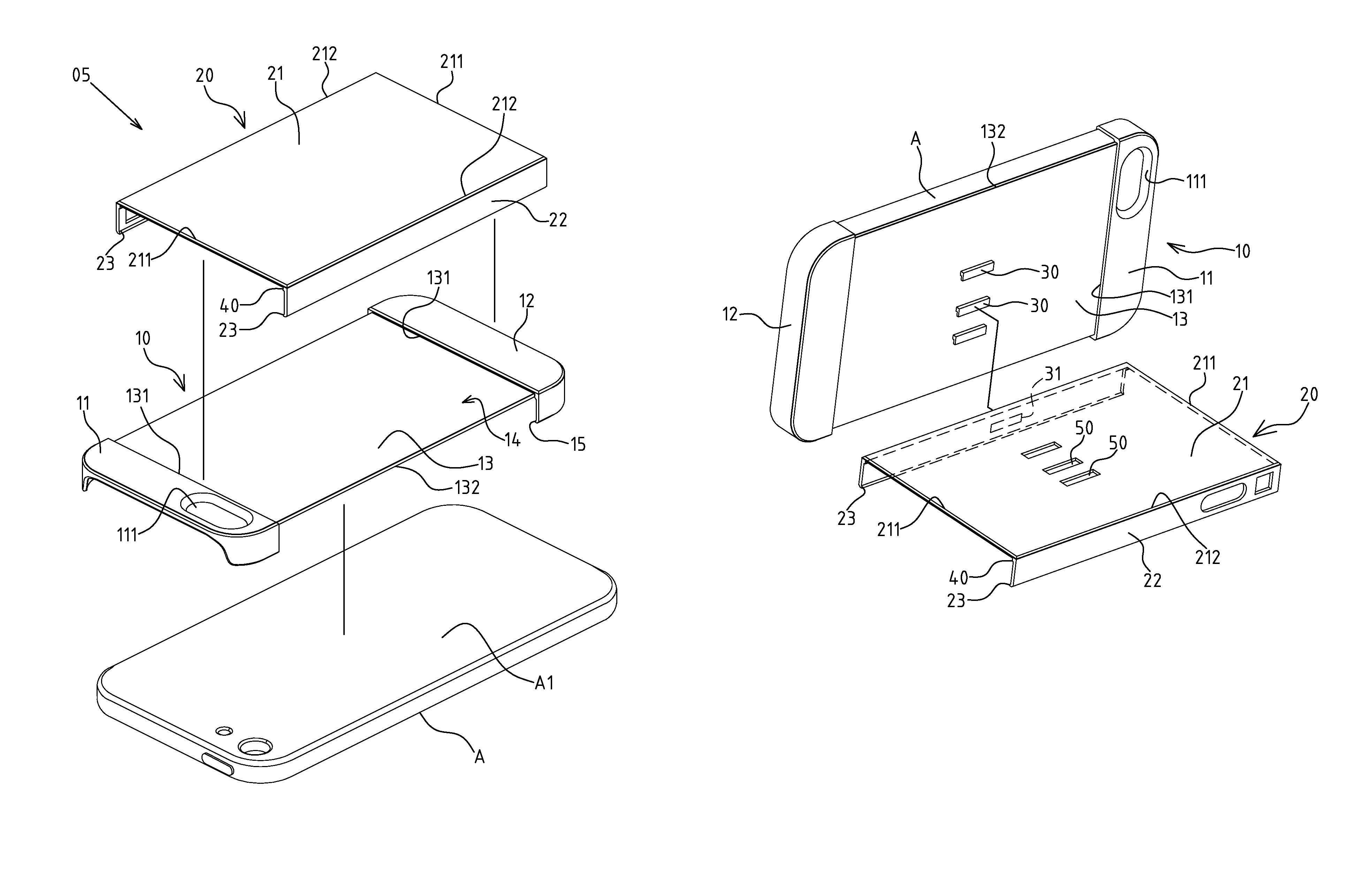
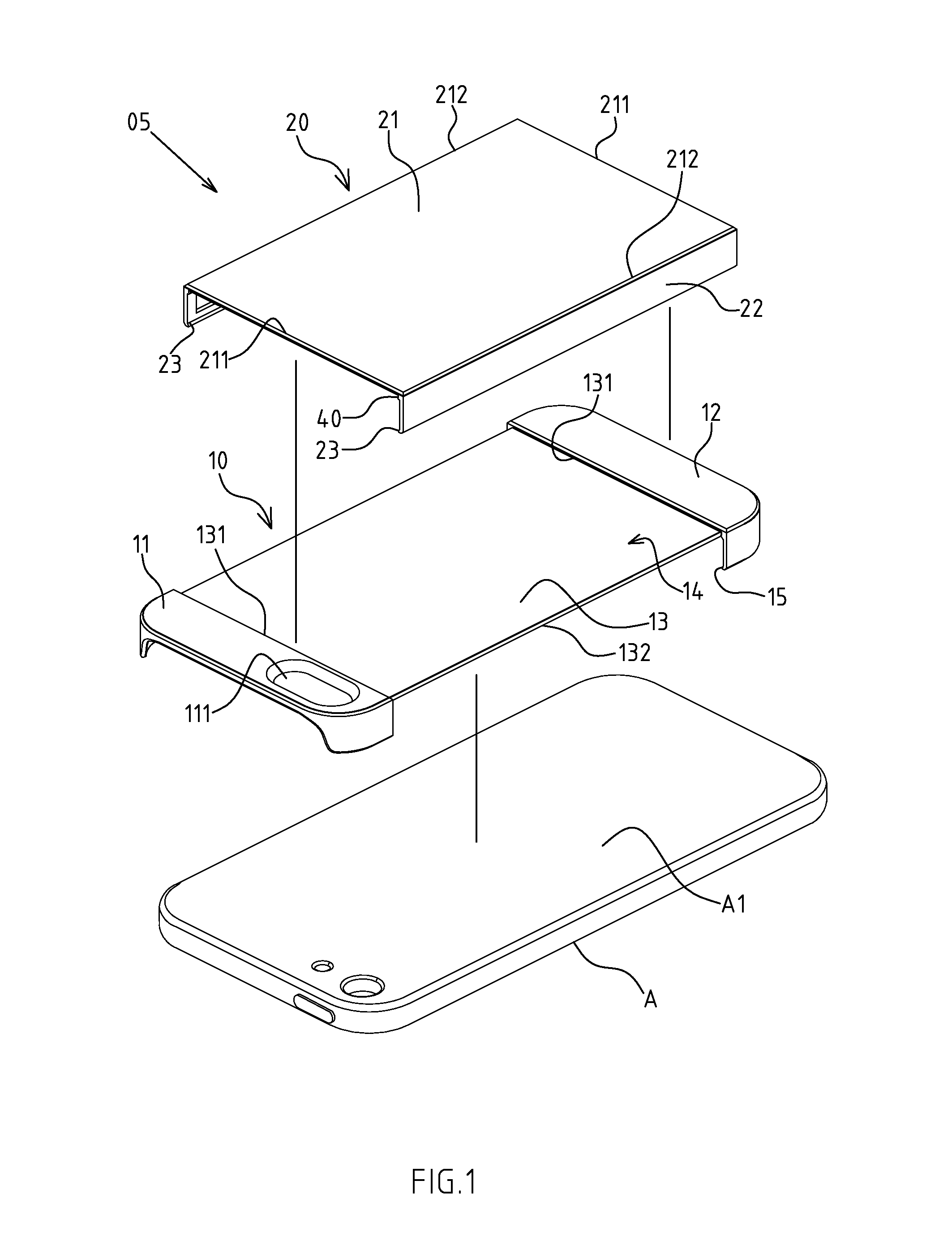
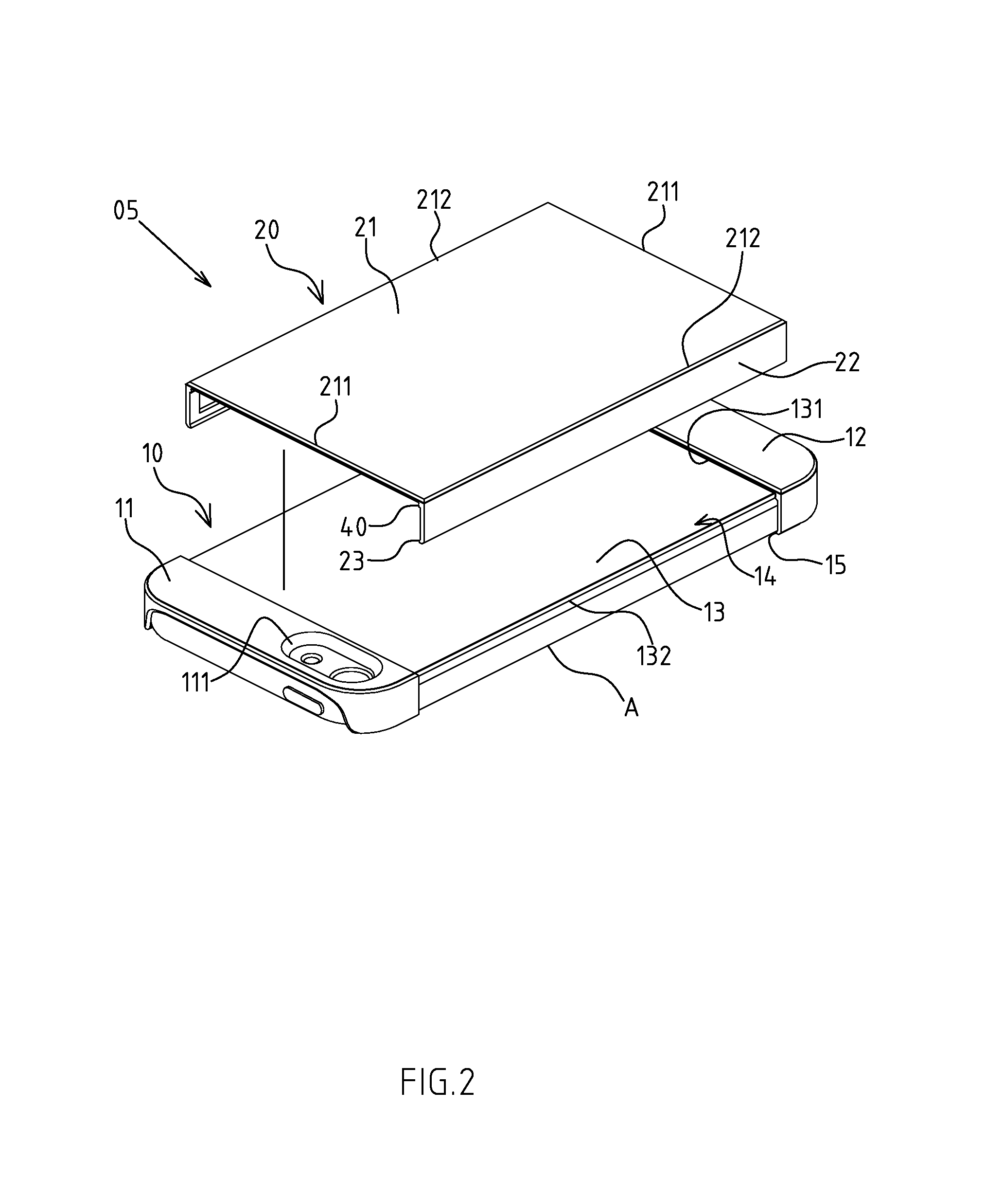
[0023]FIGS. 1-5 depict the preferred embodiments of a protective housing assembly of electronic devices of the present invention, which, however, are provided for only explanatory objective for patent claims. Said protective housing assembly 05 is attached onto the back A1 of existing electronic device A. The electronic device A of the present invention refers to any of mobile phone, portable multi-media player or tablet computer, etc.

[0024]The protective housing assembly 05 comprises a main body 10, designed into a predefined pattern, and including a front frame body 11, provided with an opening through-hole 111 at its preset location. The through-hole 111 is aligned with the camera lens or audio port, etc, preset on the electronic device A. A rear frame body 12 is set at the other side of the front frame body 11. The front and rear frame bodies 11, 12 could cover the corners and sides of the back A1 of the electronic device A. A recess plate portion 13 is arranged trans...


PUM


Abstract

The present invention provides a protective housing assembly of electronic devices, of which said protective housing assembly is attached onto the back of existing electronic device; it mainly comprising: a main body and a secondary body; of which the secondary body is arranged removably into the holding space formed by the main body; With the design of the removable structure formed by the main and secondary bodies, this enables easier replacement and assembly of the main and secondary bodies; and when the user intends to remove the protective housing assembly, only the main body or the secondary body is required to be pulled so that the first or second limiting flange is disengaged from the electronic device, thus avoiding surface damage and scratching of the electronic device; furthermore, the main and secondary bodies could be configured with different colors or patterns, permitting the users to assemble or replace them where necessary; and the disassembled main body or secondary body could be repetitively used or combined, thereby improving substantially the convenience and applicability of the electronic device while avoiding its damage or scratching.

Description


Claims


Application Information

Patent Timeline
Owner MATCH U INT
Learn More