
Stereoscopic camera for recording the surroundings

a stereoscopic camera and camera body technology, applied in the field of stereoscopic cameras, can solve the problems of image quality loss, image sensor impingement,

Active Publication Date: 2013-07-16
SILICON MICRO SENSORS
View PDF31 Cites 3 Cited by
  • Summary
  • Abstract
  • Description
  • Claims
  • Application Information

AI Technical Summary

Benefits of technology

This patent describes a stereoscopic camera that is designed to be stable and accurate even when exposed to extreme temperatures and mechanical stress. The camera uses a special mounting system that prevents any impact or movement from affecting the position of the camera's optic axis, which can cause distortion and reduce image quality. This system ensures that the camera can produce high-quality images even when in use in challenging conditions. Additionally, uncoupling the camera's lens from the circuit board reduces costs and allows for easier adjustment of the optic axis. Overall, this design prevents any compromises in the accuracy of the camera's optic axis, resulting in more reliable and accurate images.

Problems solved by technology

Therefore, a loss of image quality is detected, e.g., during extended operation of a stereoscopic camera.
These interferences are caused, on the one hand, by a displacement of the optic axes of the two recording units in reference to each other due to the different expansion of the carrier and the circuit board.
On the other hand, the interferences are caused by diffused light, which impinges an image sensor through defective connections between the carrier and the lens.
The connection between the carrier and the lens is usually adhesive connections, which can tear due to the thermal expansions of the carrier and the lens.

Method used


Image

  • Stereoscopic camera for recording the surroundings
  • Stereoscopic camera for recording the surroundings
  • Stereoscopic camera for recording the surroundings

Examples


Embodiment Construction

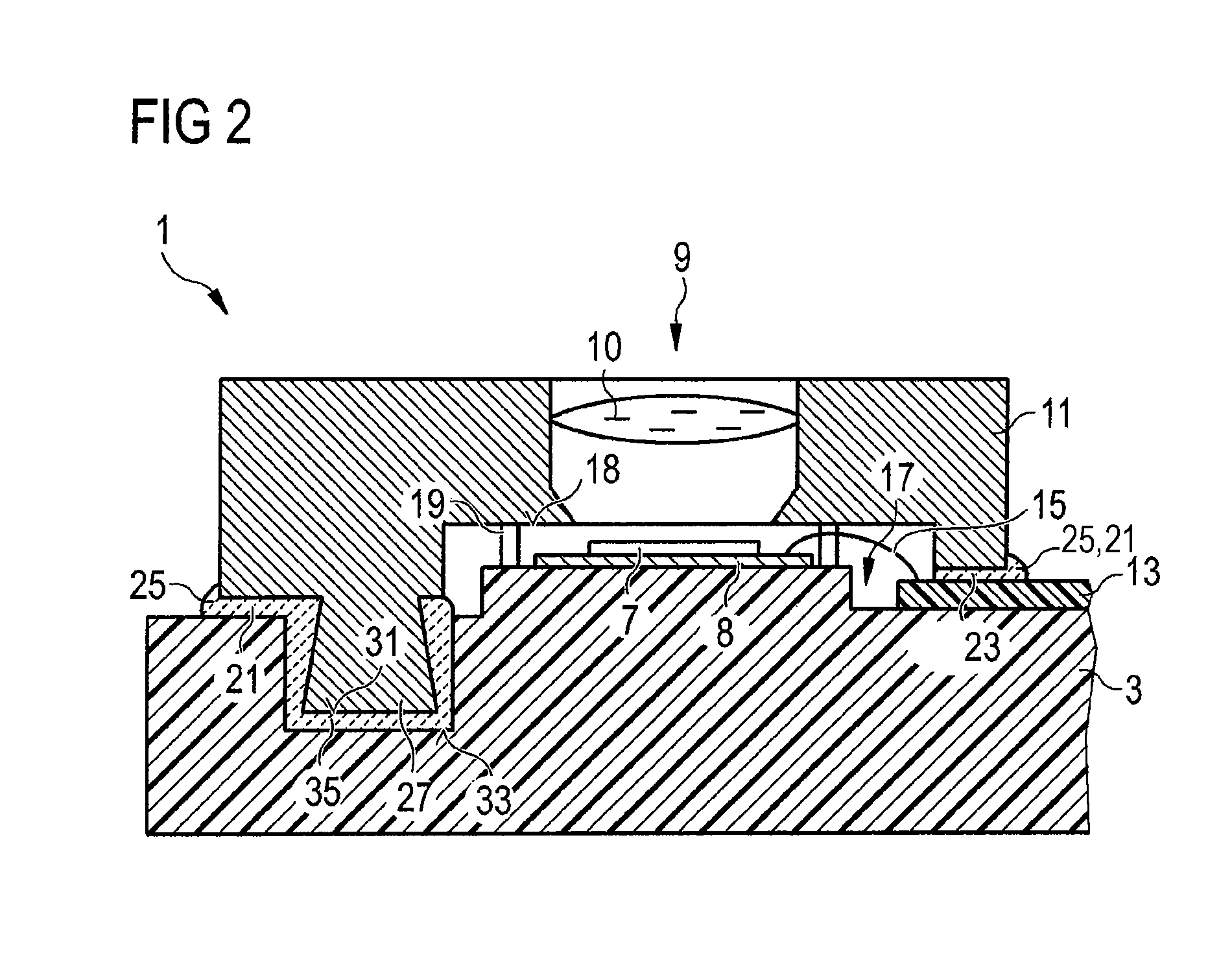
[0020]The stereoscopic camera according to FIG. 1 comprises a plate-shaped carrier 3 with a rectangular base, in the present exemplary embodiment made from stainless steel. In its longitudinal extension the carrier 3 has a pedestal 5 at the two ends located opposite each other, on which an electronic image sensor 1 is supported on a flat carrier substrate 8, not shown in greater detail. Each pedestal 5 has a support area slightly larger than the carrier substrate 8.

[0021]A lens 9 is arranged via an object fastener 11 above the image sensor 1 and at a distance therefrom. One image sensor 1 and one lens 9 each form a single imaging unit. An optic system shall be called lens 9, comprising various optic elements, such as lenses or mirrors or the like and displaying an object on the image sensor 1. The focus of the lens 9 can be adjusted in a fixed manner in various embodiments, known as a fix-focus system, or be adjustable in the installed condition, so that only after the installation ...


PUM


Abstract

A stereoscopic camera for recording the surroundings is provided with a right and a left image sensor having one lens each to display the surroundings on the image sensors, with the image sensors and the lenses being held by a carrier side-by-side and at a distance in reference to each other. The stereoscopic camera is additionally provided with a circuit board arranged on the carrier and comprising at least the signal and the supply lines of both image sensors. The image sensors are each mounted on a carrier substrate, which similar to the lenses, are arranged on the carrier and are distanced in reference to the circuit board, and have a flexible electric connection to the circuit board.

Description

CROSS-REFERENCE TO RELATED APPLICATIONS[0001]This application claims priority of German application no. 10 2007 057 172.2 filed on Nov. 26, 2007, the entire disclosure of this application is hereby incorporated herein by reference.BACKGROUND ART[0002]The invention relates to a stereoscopic camera for recording the surroundings with a right and a left image sensor, with one lens each being allocated to display the surroundings on the image sensors, with the image sensors being held by a carrier side by side and at a distance in reference to each other, and with a circuit board arranged on said carrier and provided with at least the signal and the supply lines of both image sensors.[0003]Such stereoscopic cameras are used for various applications, in order to control the movement of a mobile device based on the optic collection and processing of the three-dimensional surroundings. In order to realize the potential functions of the device, its positioning, and also to avoid collisions ...

Claims


Application Information

Patent Timeline
Patent Type & Authority Patents(United States)
IPC IPC(8): H04N5/225
CPCH04N5/2252H04N13/0239H04N13/239H04N23/51
Inventor BUSSE, ERIK
Owner SILICON MICRO SENSORS
Learn More