
Data interface process with RFID data reader glove

a technology of data interface and data reader, which is applied in the field of radio frequency identification, can solve the problems of increasing the amount of time a technician spends, consuming a user's time in non-value added tasks, and consuming non-value-added efforts. achieve the effect of reducing the time a user spends reading

Active Publication Date: 2013-07-09
THE BOEING CO
View PDF23 Cites 35 Cited by
  • Summary
  • Abstract
  • Description
  • Claims
  • Application Information

AI Technical Summary

Benefits of technology

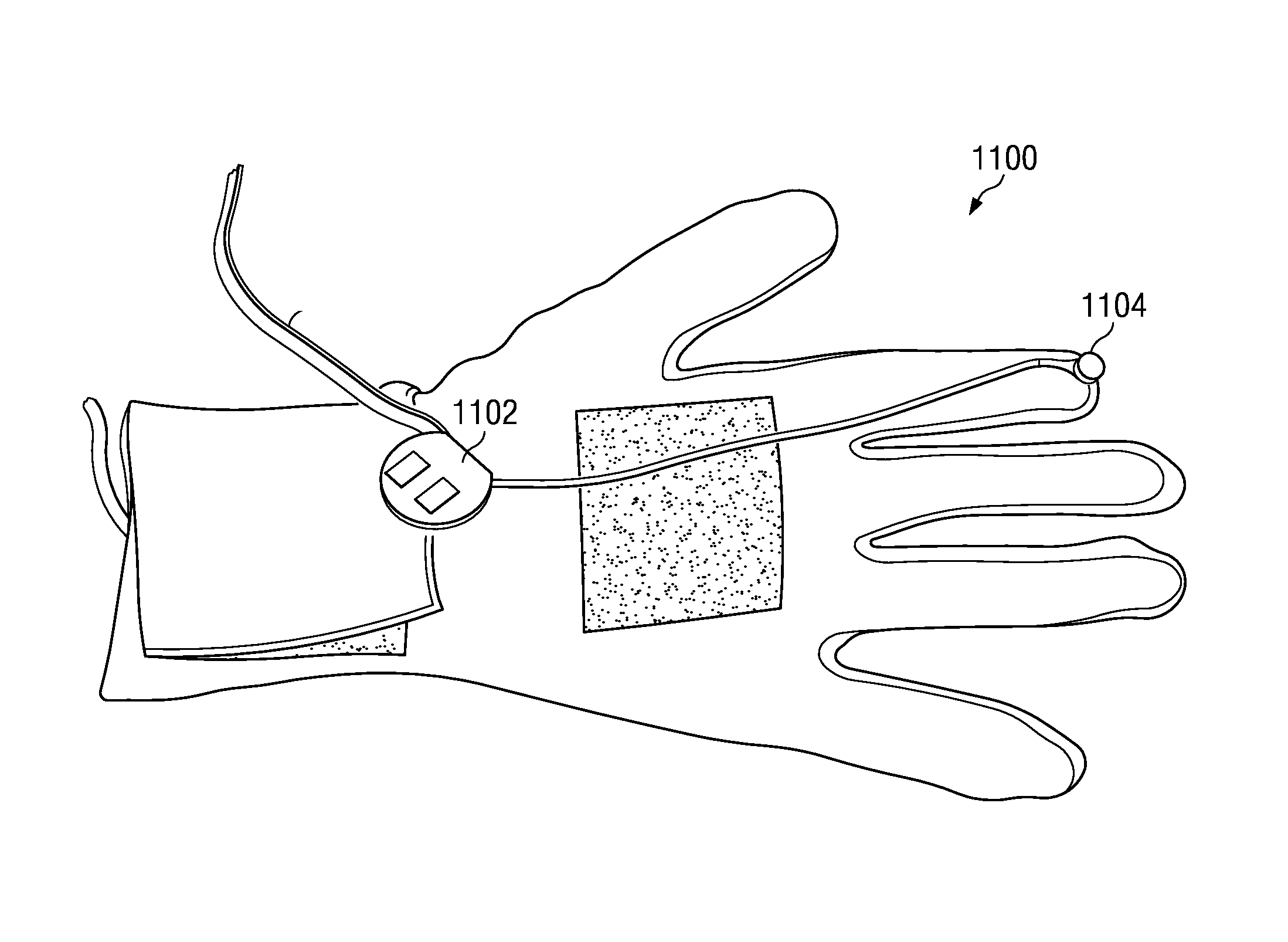
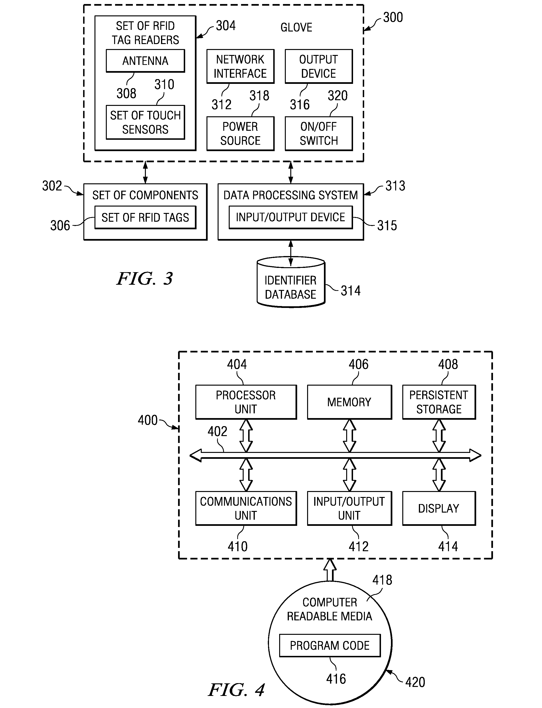
The present patent provides a method for reducing the time an aircraft assembly operator spends on non-value-added tasks by using a RFID tag reader integrated into their user apparel. This reader includes a touch activation component that can be pressed against a surface near an RFID tag associated with an aircraft component to receive data about the part through an interrogate signal. The information is displayed on a display device integrated into the apparel without interrupting the assembly task. Overall, this technology streamlines the assembly process and improves efficiency.

Problems solved by technology

Instead, operating an RFID tag reader is similar to using a meter to test voltage, in that setting up, using, then stowing the meter is a time-consuming act that yields information but does not add value to the object being tested.
Thus, increasing amounts of a technician's time is spent in performing the non-value added work of reading RFID tags.
These non-value-added efforts frequently consume a significant portion of a technician's time.
However, even small and light handheld RFID tag readers require a user to discontinue value added tasks in order to pick up, operate, and set down the device before returning to the performance of value added tasks.
Thus, handheld RFID tag readers, regardless of size, still result in consuming a user's time in non-value added tasks.

Method used


Image

  • Data interface process with RFID data reader glove
  • Data interface process with RFID data reader glove
  • Data interface process with RFID data reader glove

Examples


Embodiment Construction

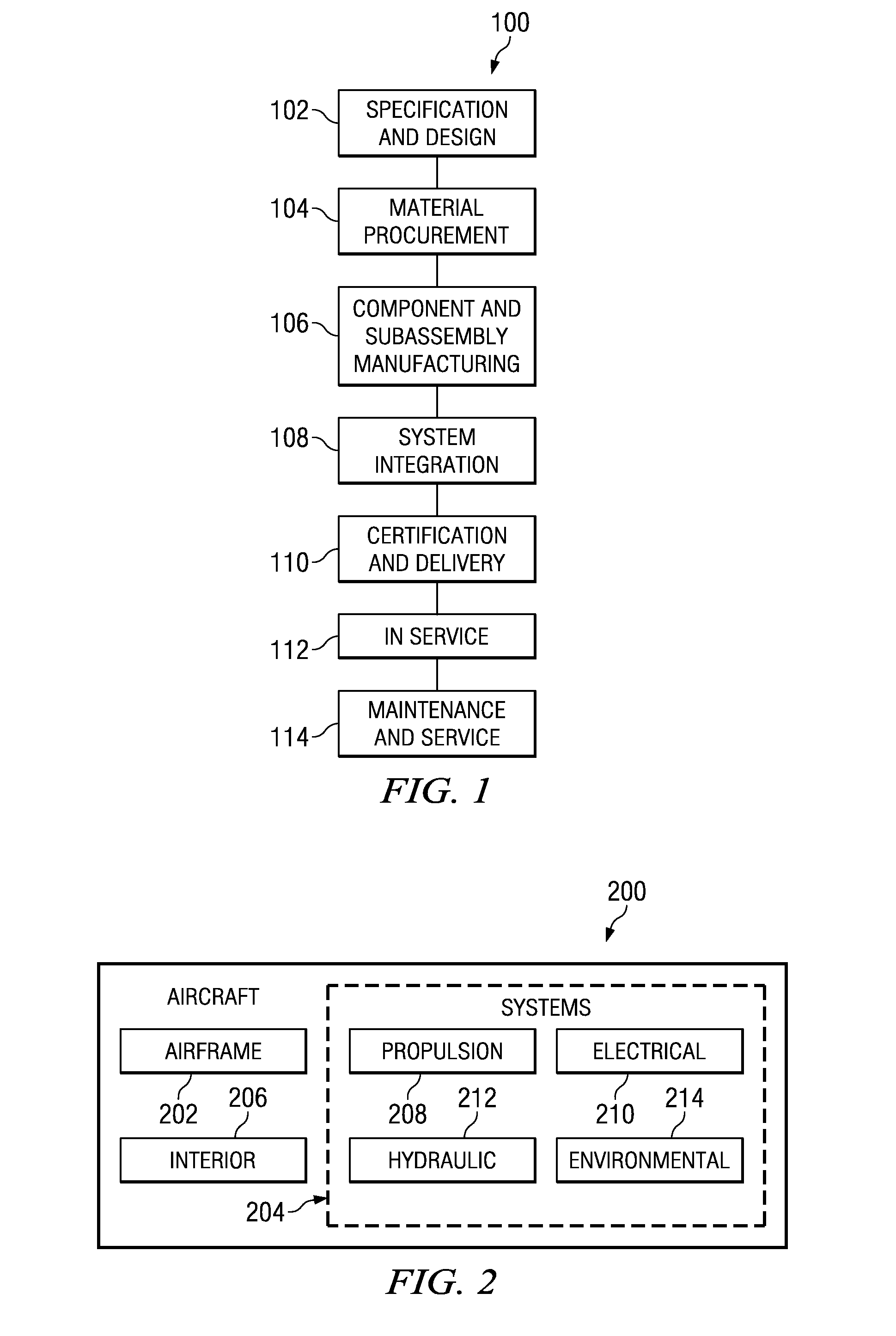
[0029]Referring more particularly to the drawings, embodiments of the disclosure may be described in the context of the aircraft manufacturing and service method 100 as shown in FIG. 1 and aircraft 200 as shown in FIG. 2. Although the embodiments are described in the context of aircraft and aircraft manufacturing, the embodiments may be used with any type of device, such as without limitation, automobiles, trucks, ships, boats, manufacturing equipment, aerospace vehicles, construction vehicles, or any other type of device. Moreover, the embodiments are not limited to manufacturing tasks. The embodiments may be used during performance of any type of task on the device, such as, without limitation, construction, maintenance, repair, testing, inspection, calibration, upgrading, or any other task performed on the device.

[0030]Turning first to FIG. 1, a diagram illustrating an aircraft manufacturing and service method is depicted in accordance with an advantageous embodiment. During pre-...


PUM


Abstract

In one embodiment, a method and apparatus for reducing time expended on non-value added tasks during assembly of an aircraft is provided. A RFID tag reading function of a RFID tag reader integrated into user apparel is enabled. The RFID tag reader comprises a set of touch activation components integrated into the user apparel. A touch activation component in the set of touch activation components is pressed against a surface in proximity of a RFID tag associated with an aircraft component. The RFID tag reader transmits an interrogate signal to an RFID tag associated with the aircraft component. The user observes a display device coupled to the RFID tag reader integrated into the user apparel, wherein the display device displays RFID tag information received from the RFID tag in response to the interrogate signal. The RFID tag information comprises data describing the aircraft component. The user receives the RFID tag information without interrupting an assembly task.

Description

BACKGROUND INFORMATION[0001]1. Field[0002]The present disclosure relates generally to radio frequency identification and in particular to radio frequency identification enabled maintenance tools. Still more particularly, the present disclosure relates to a method and apparatus for using a glove enabled with radio frequency identification and a data interface to obtain maintenance information.[0003]2. Background[0004]During performance of a manufacturing, repair, maintenance, testing, and / or inspection task on a device, such as, without limitation, an automobile or an aircraft, a technician frequently needs to review component information and other technical data associated with the device and the particular task being performed on the device. Technicians frequently use their specialized knowledge of the physical appearance of a component to locate a part name, part number, or other technical information in computer files, paper files, or microfiche files.[0005]Currently, many indust...

Claims


Application Information

Patent Timeline
Patent Type & Authority Patents(United States)
IPC IPC(8): G08B13/14B25B23/159H04Q5/22G08B23/00
CPCG06K7/0008G06K7/10118
Inventor MAJOROS, ANTHONY E.FREDGREN, BRIAN C.DAVIES, PAUL ROBERTKALINOWSKI, ROBERT DANIEL
Owner THE BOEING CO
Learn More