Extending and retracting device and vehicle step apparatus having the same
a technology of extending and retracting devices and step apparatuses, which is applied in the direction of machine supports, building scaffolds, other domestic objects, etc., can solve the problems of limiting the mounting, difficult control of the “motion” trajectory of the step member mounted on the step bracket, and restricting the travel of the step member, so as to improve the applicability of the extending and retracting device, convenient control, and high precision
- Summary
- Abstract
- Description
- Claims
- Application Information
AI Technical Summary
Benefits of technology
Problems solved by technology
Method used
Image
Examples
first embodiment
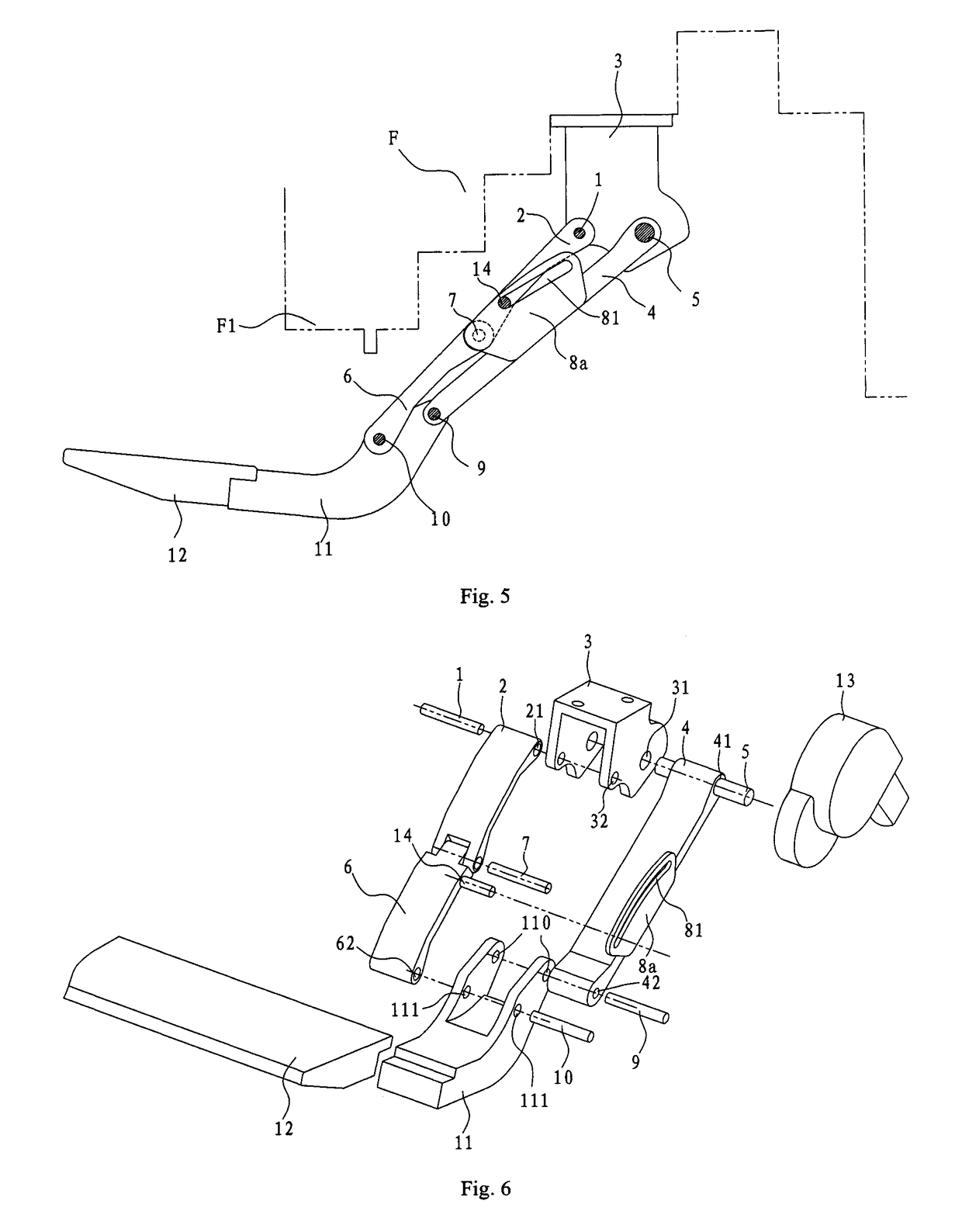
[0049]In the first embodiment as shown in FIGS. 1 through 3, the intermediate pivot 7 connecting the second end of the second arm 2 and first end of the third arm 6 is also used as the trajectory-control rod 14. In other words, the trajectory-control rod 14 and intermediate pivot 7 are the same member. A first end of the intermediate pivot 7 is inserted into and movable in the trajectory-control groove 81. A second end of the intermediate pivot 7 passes through the holes formed in the second end of the second arm 2 and first end of the third arm 6 to pivotally connect the second end of the second arm 2 and first end of the third arm 6. However, it should be appreciated by those having ordinary skill in the related art that the invention is not limited to this—for example, the trajectory-control rod 14 may be a separated member and mounted onto the second arm 2 (as shown in FIG. 4) or third arm 6 (as shown in FIG. 6), which is described below.
[0050]When the trajectory-control plate 8...
fourth embodiment
[0060]The extending and retracting device for a vehicle-step apparatus according to the invention is described below with reference to FIGS. 8 through 10.
[0061]As shown in FIGS. 8 through 10, the trajectory-control assembly includes a trajectory-control lever 8b and trajectory-control rod 14. A first end of the trajectory-control lever 8b is pivotally connected to one of the first, second, and third arms 4, 2, 6. A first end of the trajectory-control rod 14 is pivotally connected to the second end (i.e., a lower end as viewed in FIG. 8) of the trajectory-control lever 8b, and a second end of the trajectory-control rod 14 is connected to an arm opposite to the one of the first, second, and third arms 4, 2, 6 in a substantially transverse direction.
[0062]In the fourth embodiment shown in FIGS. 8 through 10, the trajectory-control lever 8b is configured as a long column, and the sides thereof have a substantially oblong shape. Through-holes 82, 83 are formed respectively in both ends o...
PUM
 Abstract
Description
Claims
Application Information
 - R&D
- Intellectual Property
- Life Sciences
- Materials
- Tech Scout
- Unparalleled Data Quality
- Higher Quality Content
- 60% Fewer Hallucinations
Browse by: Latest US Patents, China's latest patents, Technical Efficacy Thesaurus, Application Domain, Technology Topic, Popular Technical Reports.
© 2025 PatSnap. All rights reserved.Legal|Privacy policy|Modern Slavery Act Transparency Statement|Sitemap|About US| Contact US: help@patsnap.com


