
Pressurized drying system

a drying system and pressurized technology, applied in drying machines, machines/engines, light and heating equipment, etc., can solve the problems of more difficult drying of enclosed volumes for reducing water exposure, and achieve rapid and thorough drying of the interior of the structure, reducing water exposure, and reducing water exposure.

Active Publication Date: 2013-06-25
XPOWER MFG INC
View PDF108 Cites 16 Cited by
  • Summary
  • Abstract
  • Description
  • Claims
  • Application Information

AI Technical Summary

Benefits of technology

This patent describes a system for quickly and efficiently drying the inside of structures that have been exposed to water, such as flood-affected buildings. The system uses a vacuum motor to create pressure inside a housing and directs compressed air through flexible hoses to dry out enclosed spaces. The method is cost-effective and can be easily implemented to mitigate water exposure in structures.

Problems solved by technology

For example, residual moisture remaining in the interior of enclosed wall structures, e.g., between opposed panels of drywall forming part of a structure wall, are not readily accessed by existing drying equipment, thereby making the drying of these enclosed volumes for mitigation of water exposure more problematic.

Method used


Image

  • Pressurized drying system
  • Pressurized drying system
  • Pressurized drying system

Examples


Embodiment Construction

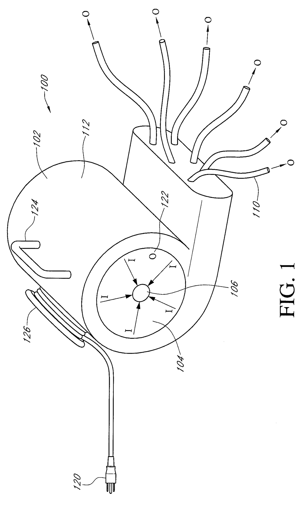
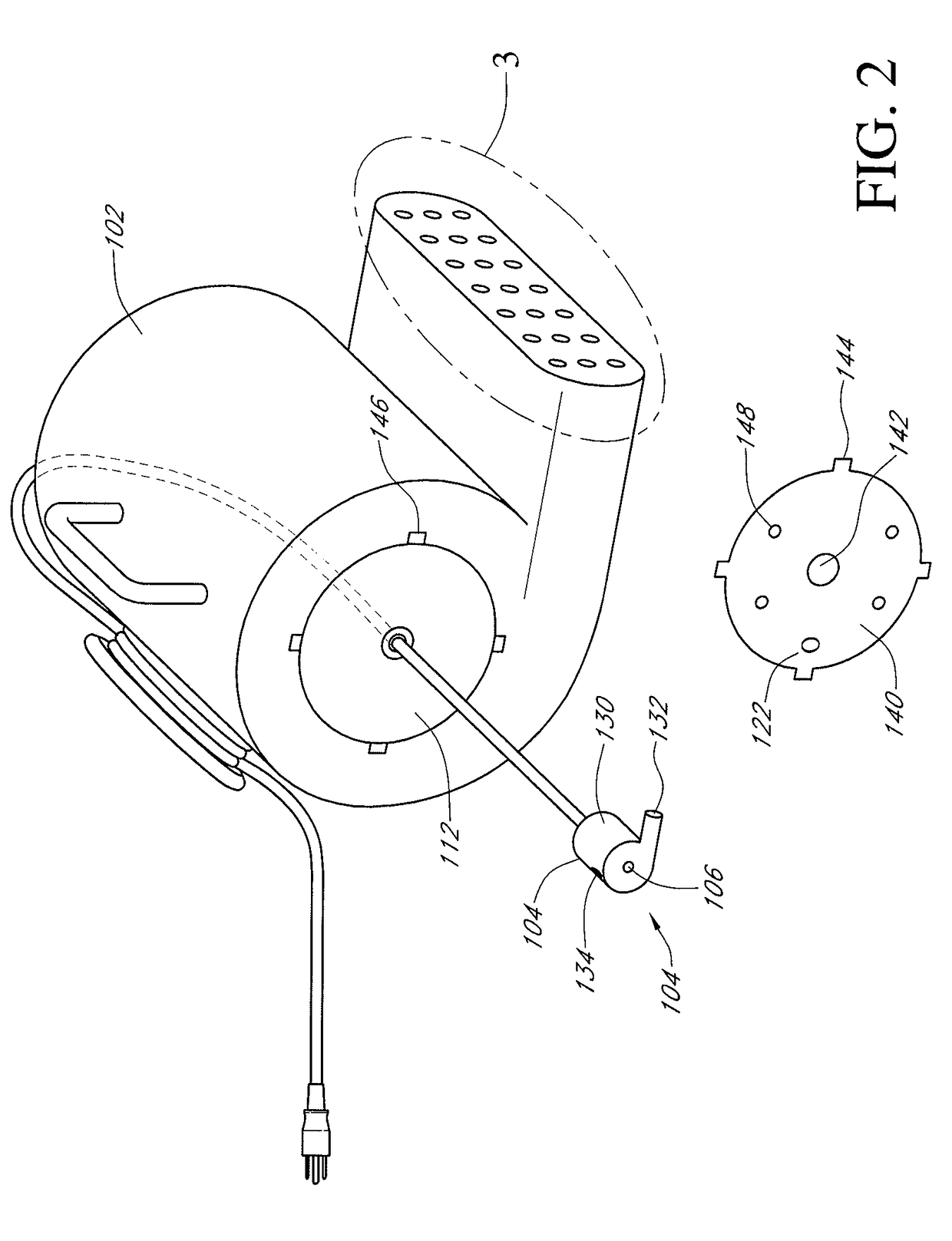
[0017]Reference will now be made to the drawings wherein like reference numerals refer to like parts of processes throughout. FIG. 1 illustrates a perspective view of one embodiment of a pressurized drying system 100. The pressured drying system 100 is configured to generate a plurality of streams of pressurized air and to direct these streams to a plurality of user selectable locations. As will be described in greater detail below following a more complete description of the components and construction of the system 100, the system 100 greatly improves the ability of users to rapidly dry the interior of structures that have been exposed to flooding or other water damage in an inexpensive and easy to use manner.

[0018]In one embodiment, the system 100 includes a generally sealed or enclosed housing 102. The housing 102 is preferably formed of a durable, strong, and relatively lightweight material and in some embodiments comprises molded plastic. The housing 102 is also preferably for...


PUM


Abstract

A system for drying structures including an enclosed housing with a plurality of outlet openings, a plurality of flexible outlet hoses each connected to a respective outlet opening, and a vacuum motor engaged with the housing such that an outlet of the vacuum motor is exhausted into an interior of the housing so as to pressurize the interior of the housing such that compressed air is directed through the plurality of outlet hoses. Also a method of drying an interior of a structure, including placing a pressurized drying system adjacent a region of a structure, forming a plurality of openings in surfaces of the structure where the surfaces define enclosed spaces, inserting distal ends of outlet hoses of the pressurized drying system into respective openings of the surfaces of the structure, and engaging the pressurized drying system so as to generate a flow of pressurized air and to direct the pressurized air into the enclosed spaces.

Description

CROSS-REFERENCE TO RELATED APPLICATIONS[0001]This application claims the priority benefits of U.S. Provisional Application 60 / 982,073 filed Oct. 23, 2007 and which is incorporated herein by reference in its entirety.BACKGROUND OF THE INVENTION[0002]1. Field of the Invention[0003]The invention relates to the field of flood / water damage remediation and to a system of providing pressurized drying air to a plurality of user selectable locations.[0004]2. Description of the Related Art[0005]Flooding or otherwise unwanted release or flow of water is a common and widespread cause of potentially expensive damages to property in many locations throughout the world. Flood damage can rise from natural sources such as overflowing rivers and lakes, rising rainwaters, rapid snow melt, mudslides, storm surges, wind-driven rain, tidal action, wave action, and the like. Water damage can also occur from malfunctions or breaks in manmade water delivery and / or storage systems. For example, broken levies...

Claims


Application Information

Patent Timeline
IPC IPC(8): F26B11/00
CPCE04B1/7092F26B9/02F26B21/001F26B21/006F26B9/003
Inventor WALKER, MARY A.WALKER, MARK S.
Owner XPOWER MFG INC
Learn More