
Dual fuel injector for a common rail system

a common rail system and fuel injector technology, applied in the direction of spray nozzles, machines/engines, mechanical equipment, etc., can solve the problems of inability to teach an injector that can independently receive two fluids, the difficulty of achieving successful ignition of gaseous fuels, and the inability to achieve safe and efficient manners

Inactive Publication Date: 2013-06-11
CATERPILLAR INC
View PDF18 Cites 29 Cited by
  • Summary
  • Abstract
  • Description
  • Claims
  • Application Information

AI Technical Summary

Benefits of technology

Enables efficient and safe independent injection of gaseous and diesel fuels, preventing mixing and ensuring precise control over injection processes, thereby improving the operational efficiency and reliability of dual fuel engines.

Problems solved by technology

However, gaseous fuels are well known for the difficulty in attaining successful ignition.
Fuel systems capable of independently injecting both a gaseous fuel and a diesel fuel in a manner that is both safe and efficient has proven to be elusive.
However, this reference fails to teach an injector that can independently receive two fluids, keep those fluids separate, and independently control the injection of the fluids.

Method used


Image

  • Dual fuel injector for a common rail system
  • Dual fuel injector for a common rail system
  • Dual fuel injector for a common rail system

Examples


Embodiment Construction

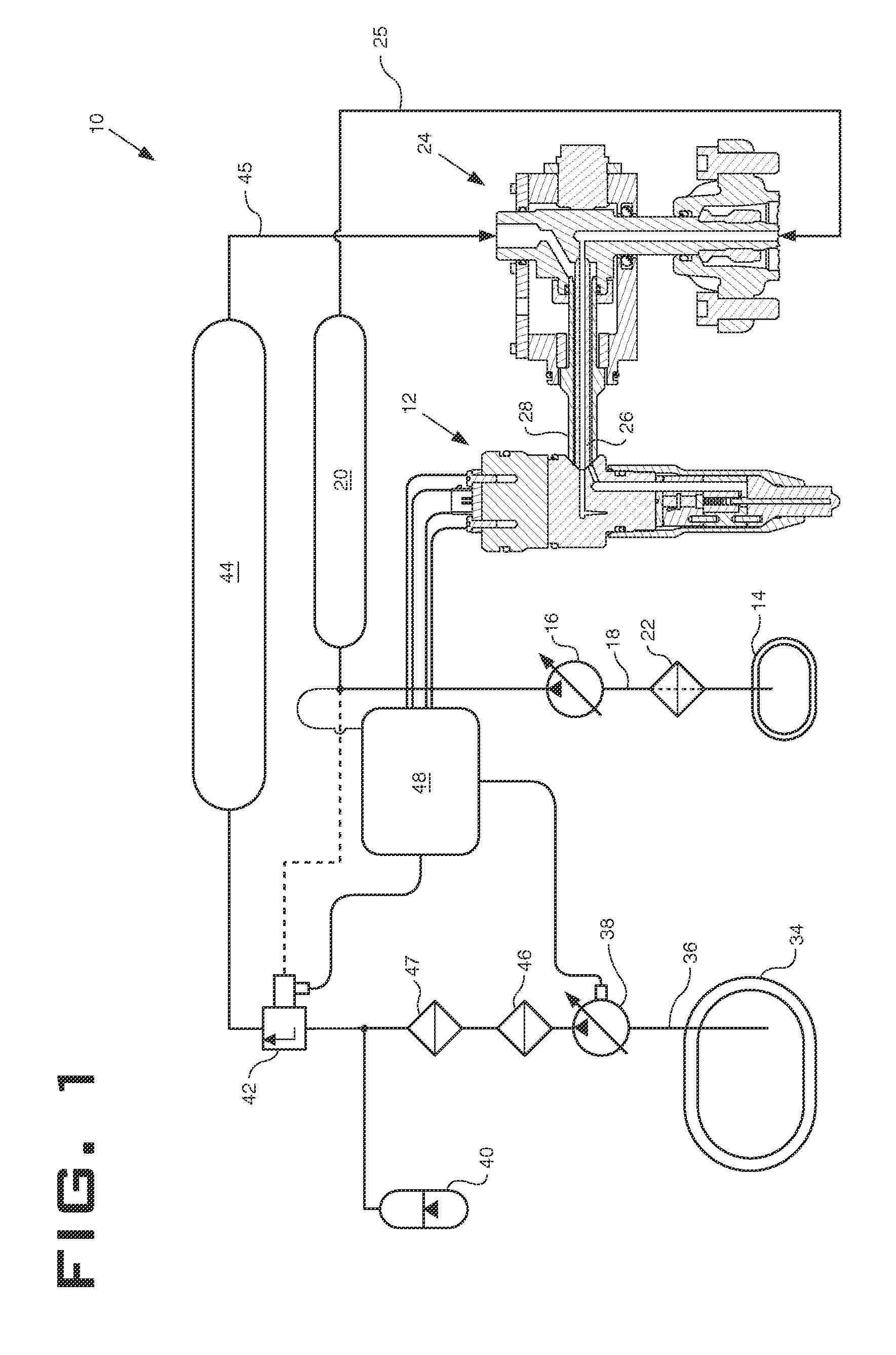
[0011]Referring to FIG. 1, a fuel system 10 utilizing a dual fuel common rail injector 12 is shown. For ease of discussion, the dual fuel common rail injector will be referred to as “injector 12”. A diesel fuel source 14 contains diesel fuel. A diesel pump 16 draws diesel fuel through diesel supply line 18; pressurizes the diesel fuel; and delivers the pressurized diesel fuel to a diesel fuel rail 20. A filter 22 may be disposed in the diesel supply line 18 upstream of the diesel pump and downstream of the diesel fuel source 14. Diesel fuel within the diesel fuel rail 20 may be pressurized to a pressure of approximately 40 MPa. Pressurized diesel fuel from the diesel fuel rail 20 may then be delivered to a quill assembly 24 via diesel fuel line 25. Quill assembly 24 is configured to receive both diesel fuel and a gaseous fuel such as liquid natural gas. Those skilled in the art will recognize that the gaseous fuel may be any gaseous fuel such as natural gas, propane, methane, liquef...


PUM


Abstract

A dual fuel common rail fuel injector includes a first and second control valve assembly and a first and second check needle. The dual fuel injector is capable of selectively injecting two different fuels such as diesel and liquid natural gas. The first and second control valve assemblies operate using a single fuel, such as diesel, as the control medium. The dual fuel common rail injector further includes a hydraulic lock assembly.

Description

TECHNICAL FIELD[0001]The present disclosure relates generally to dual fuel common rail systems, and more particularly to a fuel injector configured to receive two separate fluids and selectively inject the fluids independent of one another.BACKGROUND[0002]Gaseous fuel engines are known for their ability to burn relatively clean relative to their compression ignition engine counterparts. However, gaseous fuels are well known for the difficulty in attaining successful ignition. Some gaseous fuel engines utilize a spark plug, whereas other engines are known for utilizing a small amount of distillate diesel fuel that is compression ignited to in turn ignite a larger charge of gaseous fuel. Fuel systems capable of independently injecting both a gaseous fuel and a diesel fuel in a manner that is both safe and efficient has proven to be elusive. U.S. Pat. No. 4,499,862 issued to Baumer, et al. sought to address this issue. However, this reference fails to teach an injector that can indepen...

Claims


Application Information

Patent Timeline
Patent Type & Authority Patents(United States)
IPC IPC(8): F02M51/06F02M21/00F02M47/02F02M21/02F02M43/04
CPCF02D19/0647F02D19/0689F02D19/0694F02M43/02F02M43/04F02M47/027F02M63/0017F02M63/0033F02M63/0043F02M63/0064F02D19/061F02D19/105F02B3/06F02M2200/02F02M2200/28F02M2200/44F02M2200/701Y02T10/36Y02T10/30
Inventor KIM, HOISANSOMMARS, MARKDING, XIANGDONG
Owner CATERPILLAR INC
Learn More