
Frame unit of a curtain wall

a frame unit and curtain wall technology, applied in the field of frame units, can solve the problems of increasing the cost of material and manufacture of mullions, inconvenient assembly of conventional frame units, and time-consuming, and achieve the effect of enhancing the structural strength of curtain walls

Inactive Publication Date: 2013-06-04
HUANG RONG JUN
View PDF20 Cites 37 Cited by
  • Summary
  • Abstract
  • Description
  • Claims
  • Application Information

AI Technical Summary

Benefits of technology

The technical effect of this patent is to provide a frame unit for a curtain wall that strengthens its structure. The frame unit includes a mullion, a beam, and a connecting device. By using a separate connecting device with two groups, forces can be spread out to multiple mullions, resulting in a stronger curtain wall.

Problems solved by technology

The thickness and width of the conventional mullions 92,R2 have to be enlarged to bear the wind loads, but this will increase the costs for material and manufacture of the mullions 92,R2.
Additionally, the structure of the conventional frame unit is complicated and the assembling of the conventional frame units is inconvenient and time consumptive.

Method used


Image

  • Frame unit of a curtain wall
  • Frame unit of a curtain wall
  • Frame unit of a curtain wall

Examples


first embodiment

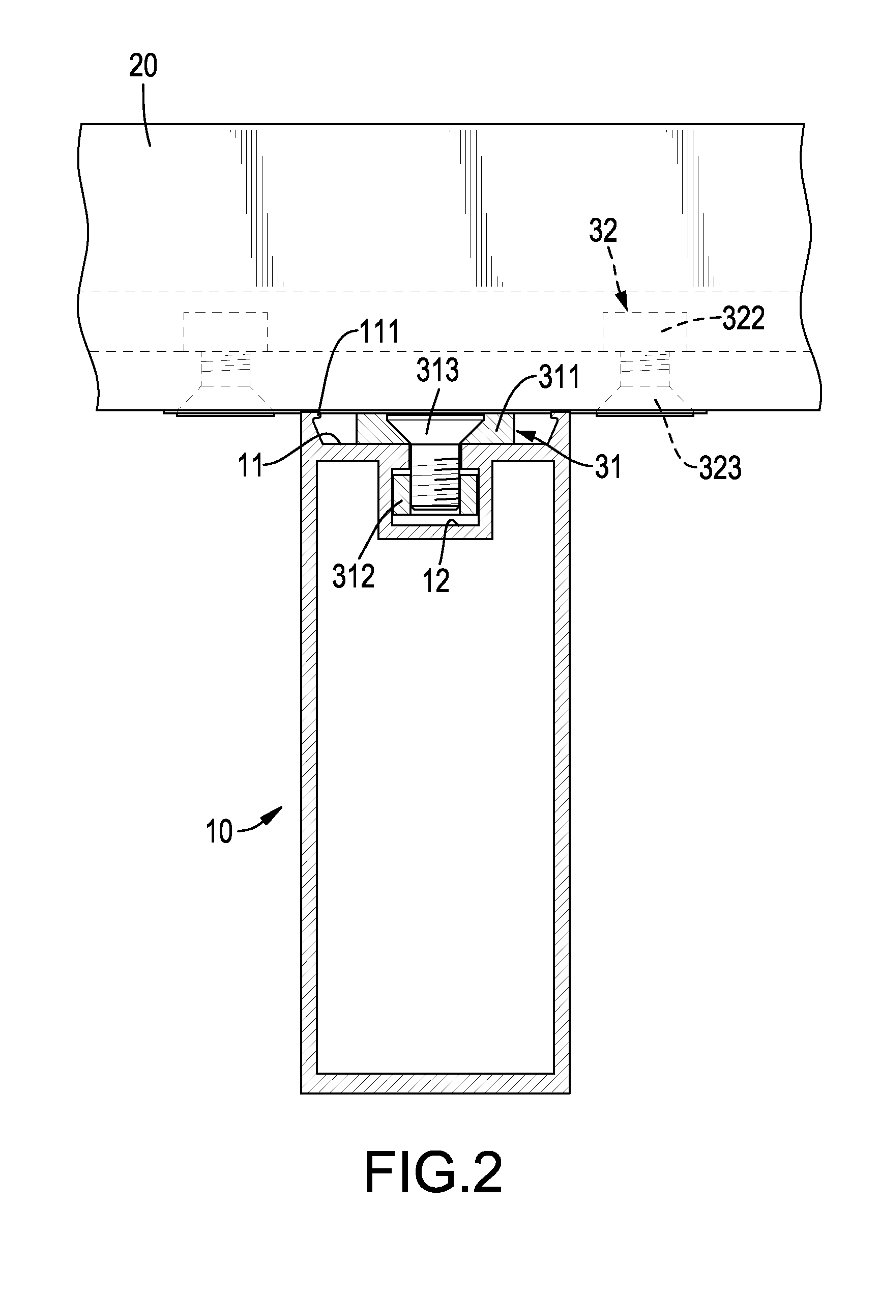
[0026]With reference to FIGS. 1 to 3, a frame unit of a curtain wall in accordance with the present invention comprises a mullion 10, a beam 20 and a connecting device 30.

[0027]The mullion 10 is an elongated member and has a top surface, a bottom surface, a side surface, a linear mullion recess 11 and a linear mullion channel 12.

[0028]The mullion recess 11 is formed in the side surface of the mullion 10, is formed through the top surface and the bottom surface of the mullion 10 and has an opening, two opposite inner surfaces, a bottom, two clamping sections 111 and an extending length.

[0029]The bottom of the mullion recess 11 has a width. The opening of the mullion recess 11 has a width and two opposite edges. Preferably, the width of the opening of the mullion recess 11 is larger than that of the bottom of the mullion recess 11. Each inner surface of the mullion 10 leans from the bottom of the mullion recess 11 to the opening of the mullion recess 11.

[0030]The clamping sections 111...

fourth embodiment

[0054]The curtain wall implemented by the frame units is defined as a first curtain wall W1.

second embodiment

[0055]With further reference to FIG. 9, multiple sticks 70C are respectively inserted into the stick recesses 23C, 52C of the beams 20C and the beam covers 50C. Each stick 70C is linear and has two ends respectively inserted into two adjacent first curtain walls W1. With the sticks 70C, multiple first curtain walls W1 can be connected to form the curtain wall. Consequently, the mullions 10C may be visible from both the exterior O and the interior I of the connected curtain walls W1.

[0056]With reference to FIGS. 10 and 11, a third embodiment of the curtain wall implemented by multiple frame units in FIG. 8 is substantially the same as the second embodiment of the curtain wall except that some of the sticks 70D are L-shaped. The curtain walls in FIGS. 10 and 11 are defined as second curtain walls W2.

[0057]The L-shaped sticks 70D connect two adjacent second curtain walls W2 perpendicularly with each other. With the linear and L-shaped sticks 70C,70D, the format of the connected curtain...


PUM


Abstract

A frame unit of a curtain wall has a mullion, a beam and a connecting device. The mullion has a mullion recess and a mullion channel. The beam is substantially the same as the mullion and has a beam recess and a beam channel. The connecting device has a first group and a second group. The first group has a plate, two chunks and two bolts. The plate is mounted in the mullion recess. The chunks are mounted in the mullion channel. The bolts are mounted through the plate and are respectively screwed into the chunks. The second group is the same as the first group and is similarly connected with the beam. Because one beam can be connected with and spreads forces to multiple mullions, a structure of a curtain wall can be enhanced.

Description

BACKGROUND OF THE INVENTION[0001]1. Field of the Invention[0002]The present invention relates to a frame unit, and more particularly to a frame unit of a curtain wall to enhance the structural strength of the curtain wall.[0003]2. Description of Related Art[0004]With reference to FIG. 13, a conventional frame unit 90 of a curtain wall has one beam 91 and one mullion 92. Two opposite sides of the mullion 92 are respectively connected with the beam 91 and a beam 91 of another frame unit 90. With reference to FIG. 14, another conventional frame unit R of a curtain wall has a beam R1 and a mullion R2 with which an end of the beam R1 is securely connected. Multiple frame units R can be assembled with multiple plates of glass to form a curtain wall.[0005]However, the beam 91,R1 of the conventional frame unit 90,R has to be mounted between and connected with two mullions 92,R2, and two ends of one beam 91,R1 cannot be connected with more than two mullions 92,R2. The curtain wall cannot bea...

Claims


Application Information

Patent Timeline
Patent Type & Authority Patents(United States)
IPC IPC(8): E04H14/00
CPCE04B2/96
Inventor HUANG, RONG-JUN
Owner HUANG RONG JUN
Learn More