
Drawer mechanism and image forming apparatus equipped with the same

a technology of drawing mechanism and image forming apparatus, which is applied in the direction of electrographic process apparatus, instruments, printing, etc., can solve the problems of increasing cost and weight, large number of components, so as to reduce the number of components and cost, reduce the number of fabrication man-hours, and reduce the resistance load

Inactive Publication Date: 2013-05-28
KYOCERA DOCUMENT SOLUTIONS INC
View PDF8 Cites 3 Cited by
  • Summary
  • Abstract
  • Description
  • Claims
  • Application Information

AI Technical Summary

Benefits of technology

[0011]An object of the invention is to provide a drawer mechanism that is made compact and reduces the fabrication man-hours, the number of components, and the cost while making the resistance load smaller. Another object is to provide an image forming apparatus equipped with this drawer mechanism.

Problems solved by technology

Hence, the number of components is large and the cost and the weight are increased.
Hence, as with the apparatus of D1, the number of components is large and the cost and the weight are increased.
Hence, this configuration is not preferable for a drawer mechanism adopted in an image forming apparatus because the respective units therein are heavy components and resistance load becomes larger.

Method used


Image

  • Drawer mechanism and image forming apparatus equipped with the same
  • Drawer mechanism and image forming apparatus equipped with the same
  • Drawer mechanism and image forming apparatus equipped with the same

Examples


Embodiment Construction

[0027]Hereinafter, one embodiment of the invention will be described in detail with reference to the drawings.

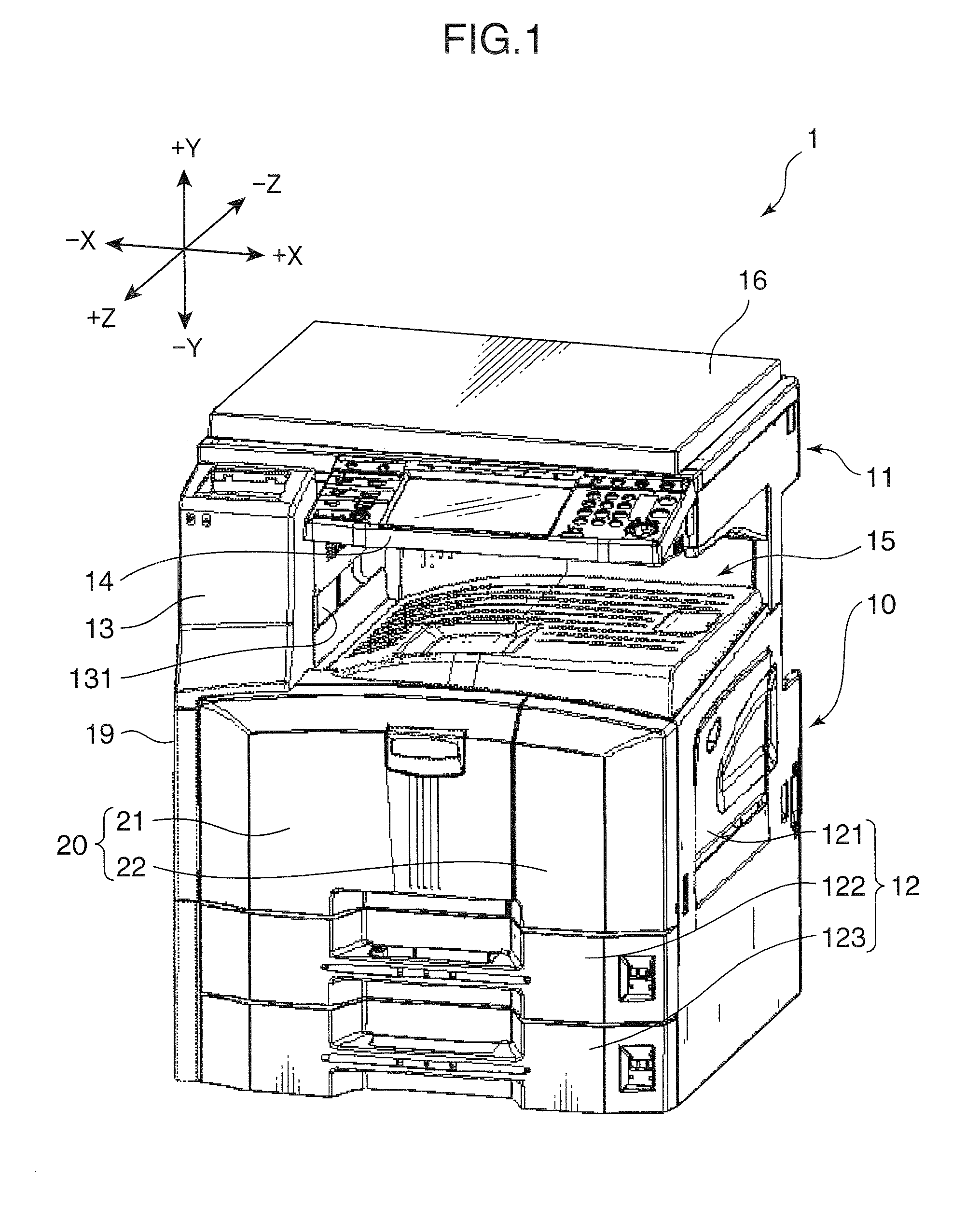
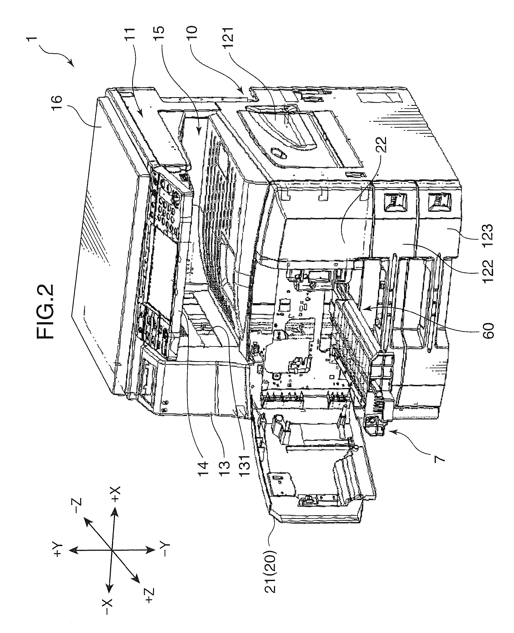
[0028]FIG. 1 is a perspective view showing the outward appearance of an image forming apparatus 1 according to one embodiment of the invention. FIG. 2 is also an outward perspective view of the image forming apparatus 1 showing a state where a front cover 20 is open and a paper feeding unit 7 is pulled out. In these drawings, the X direction is referred to as the right-left direction (+X is the right and −X is the left), the Y direction is referred to as the top-bottom direction (+Y is the top and −Y is the bottom), and the Z direction is referred to as the front-rear direction (+Z is the front and the −Z is the rear).

[0029]The image forming apparatus 1 is a copying machine of a so-called body-inside paper discharging type, and it includes an apparatus main body 10, a scanner unit 11 disposed above the apparatus main body 10, and a paper discharging portion 15 disposed betwe...


PUM


Abstract

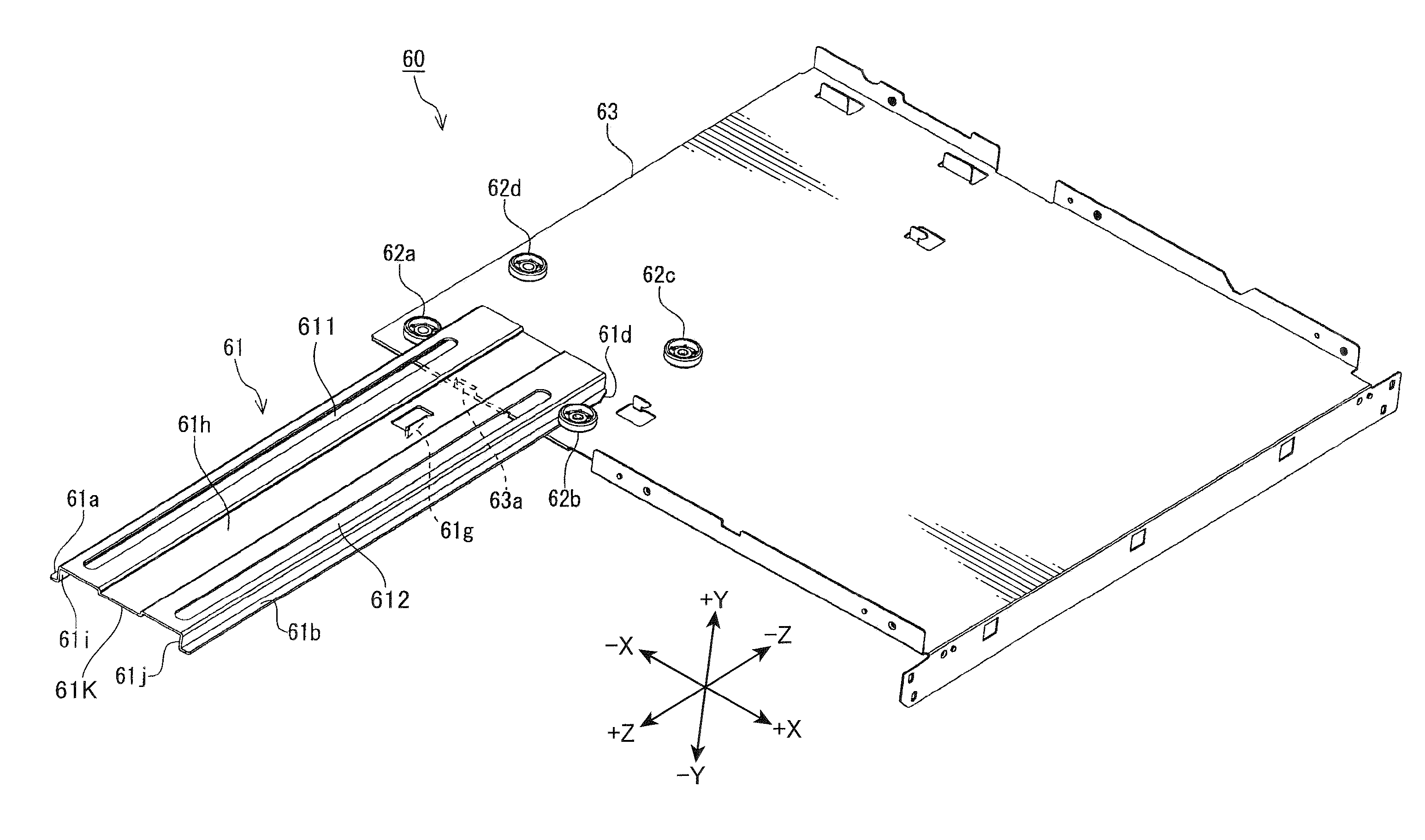
A drawer mechanism includes a plate-shaped frame, a first roller and a second roller disposed in a rotatable manner on a surface of the frame at a specific interval, and a rail movable between a first state where the rail is mounted on the surface of the frame and a second state where the rail is pulled out from the frame in a predetermined pull-out direction. Each roller includes a guide peripheral surface formed in an outer peripheral portion in a radial direction and a lower surface opposing the surface of the frame at a specific interval. The rail includes a first pinched portion and a second pinched portion extending linearly in the pull-out direction and pinched between the surface of the frame and one of the lower surfaces and the guide peripheral surfaces of the first roller and the second roller, respectively.

Description

BACKGROUND OF THE INVENTION[0001]1. Field of the Invention[0002]The present invention relates to a drawer mechanism that allows units to be pulled out from a certain apparatus main body and to an image forming apparatus equipped with the same.[0003]2. Description of the Related Art[0004]An image forming apparatus, such as a copying machine, is often configured in such a manner that respective units can be pulled out in order to facilitate maintenance. Units that can be pulled out include a paper feeding cassette, a primary paper feeding unit, an intermediate feed unit, a developing unit, a drum unit, a toner container, and a discharge unit. During paper jam processing or at the occurrence of empty toner or empty paper, the user is able to carry out the task by pulling out the corresponding unit. Various types have been proposed regarding the mechanism that allows units to be pulled out, of which a typical mechanism adopting a rail will now be described by way of example.[0005]Accord...

Claims


Application Information

Patent Timeline
Patent Type & Authority Patents(United States)
IPC IPC(8): B41J29/02
CPCG03G21/1623G03G2221/1684
Inventor NOGUCHI, YOUHEI
Owner KYOCERA DOCUMENT SOLUTIONS INC
Learn More