
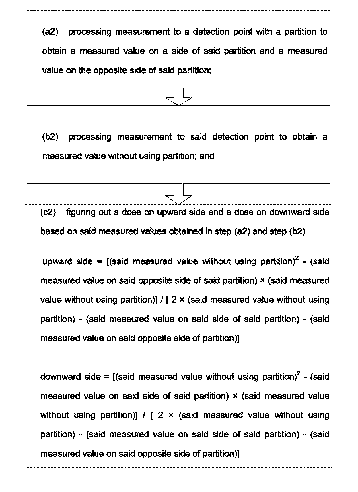
Method of measuring radiation doses on different directions

a radiation dose and radiation measurement technology, applied in the direction of optical radiation measurement, luminescent dosimeters, instruments, etc., can solve the problems of not being able to be used not being able to meet the requests of all users on actual use, and not being able to use in a small room

Inactive Publication Date: 2013-05-14
INST NUCLEAR ENERGY RES ROCAEC
View PDF5 Cites 21 Cited by
  • Summary
  • Abstract
  • Description
  • Claims
  • Application Information

AI Technical Summary

Benefits of technology

This method enables accurate measurement of radiation doses in different directions, overcoming the limitations of existing tools by providing detailed directional data without the complexity of using thick shields, making it suitable for various environments, including small rooms.

Problems solved by technology

However, they only measure the sum of the radiation doses on all directions.
1. Although the radiation detector may be directional, it only means the radiation detector has different sensitivities to radiation on different direction. For example, the radiation detector may receive 100% radiation on the front and only 80% radiation on its side. The radiation dose thus measured is basically a dose sum without varying each dose on each direction.
2. TLD only receives and sums up radiation doses on different directions yet does not vary the doses on different directions.
3. A thick shield may be used for measuring a radiation dose on a certain direction by blocking radiation from the other directions. But, the operation may become complex, and it may not be possible to be used in a small room.
Hence, the prior arts do not fulfill all users' requests on actual use.

Method used


Image

  • Method of measuring radiation doses on different directions
  • Method of measuring radiation doses on different directions
  • Method of measuring radiation doses on different directions

Examples


Embodiment Construction

[0015]The following descriptions of the preferred embodiments are provided to understand the features and the structures of the present disclosure.

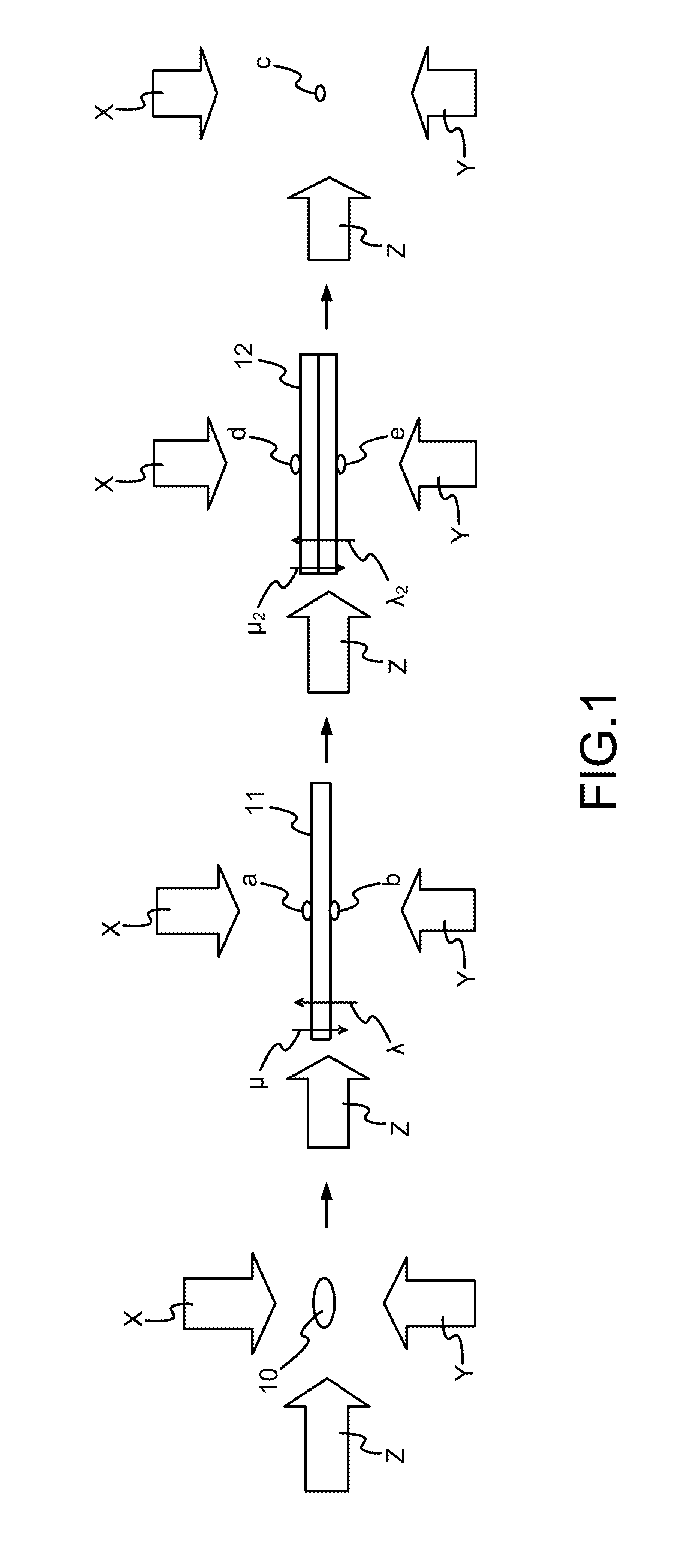
[0016]FIG. 1 shows a first preferred embodiment according to the present disclosure. As shown in the figure, the present disclosure is a method of measuring radiation doses on different directions, comprising the following steps:

[0017](a1) At a detection point 10, a measurement is processed to measure doses above and below surfaces of a single partition 11. Thus, a measured value {a} above the single partition 11 and a measured value {b} below the single partition 11 are obtained while the single partition 11 is placed facing upward and downward with an attenuation ratio {μ} to a dose on upward side of the single partition 11 and an attenuation ratio {λ} to a dose on downward side of the single partition 11.

[0018](b1) At the detection point 10, a measurement is processed to measure doses above and below surfaces of a dual-partition 12. Th...


PUM


Abstract

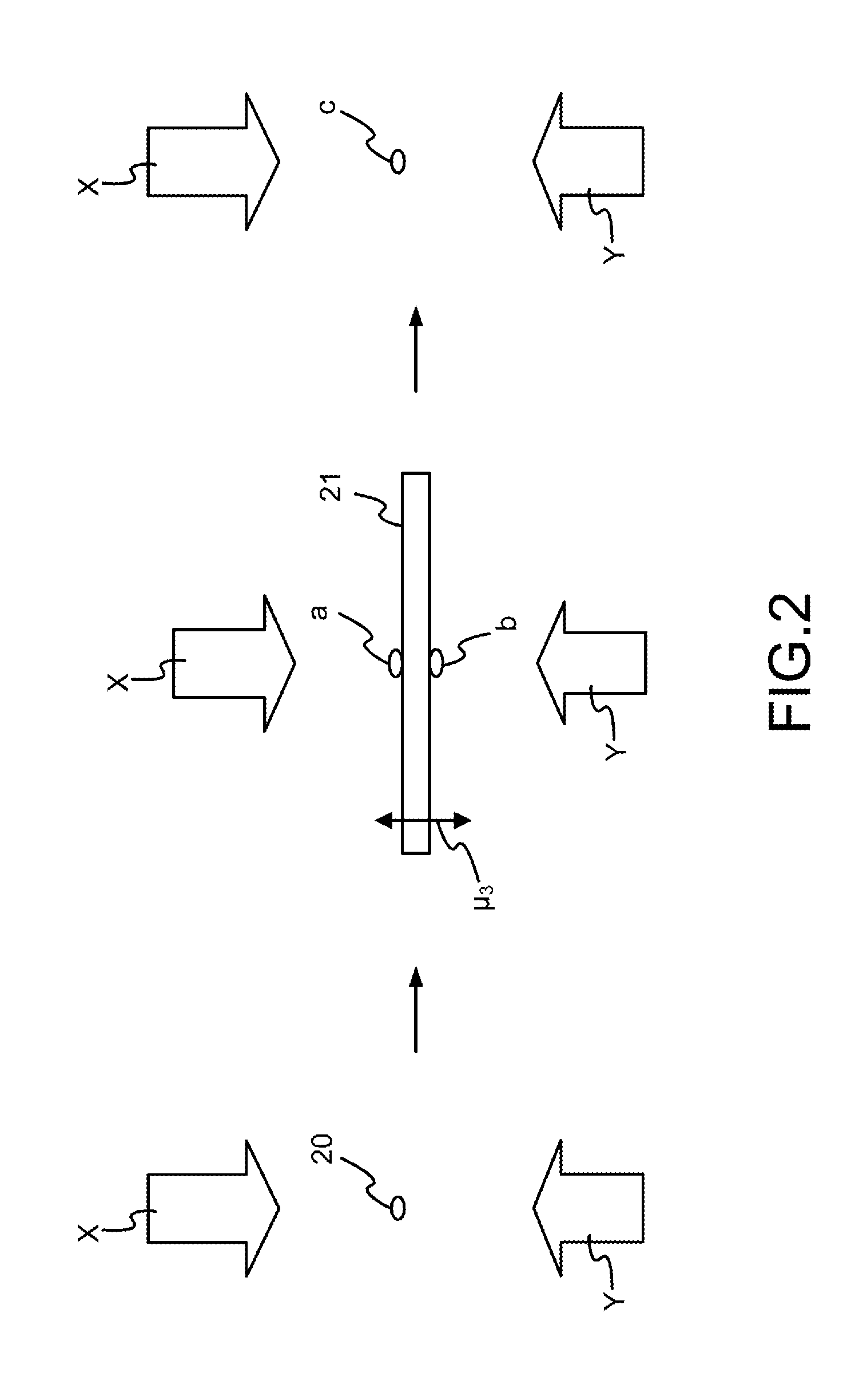
The present disclosure measures radiation doses on different directions. A partition is used, which has a certain attenuation ratio. With the partition, radiation doses on different directions can be determined without knowing the thickness or material of the partition.

Description

TECHNICAL FIELD OF THE DISCLOSURE[0001]The present disclosure relates to measuring radiation dose, and more particularly, relates to using a partition having attenuation for measuring radiation doses on different directions.DESCRIPTION OF THE RELATED ARTS[0002]In a radiation environment, a radiation dose check at a detection point has to be done regularly. Equipment used for checking the radiation dose include radiation detector and thermoluminescent dosimeter (TLD). However, they only measure the sum of the radiation doses on all directions.[0003]Yet, in some cases, dose on a certain direction has to be acquired. For example, on removing a nuclear facility, an effect of radiation dose on moving or destructing equipment at a certain direction has to be known. But, common tools used for detecting doses on different directions have the following problems:[0004]1. Although the radiation detector may be directional, it only means the radiation detector has different sensitivities to rad...

Claims


Application Information

Patent Timeline
Patent Type & Authority Patents(United States)
IPC IPC(8): G01T1/02G06F17/40G06F19/00G01D1/16G01J5/00
CPCG01T1/11
Inventor CHEN, YI-CHANGLEE, LUN-HUI
Owner INST NUCLEAR ENERGY RES ROCAEC
Learn More