
Wide band digital receiver: system and method

a digital receiver and wide band technology, applied in transmission systems, instruments, code conversion, etc., can solve the problems of fundamental performance limits of conventional electronic adcs (eadcs) significantly constraining the potential of these systems, and conventional eadcs do not have sufficient bandwidth

Active Publication Date: 2013-05-14
ROCKWELL COLLINS INC
View PDF8 Cites 23 Cited by
  • Summary
  • Abstract
  • Description
  • Claims
  • Application Information

AI Technical Summary

Benefits of technology

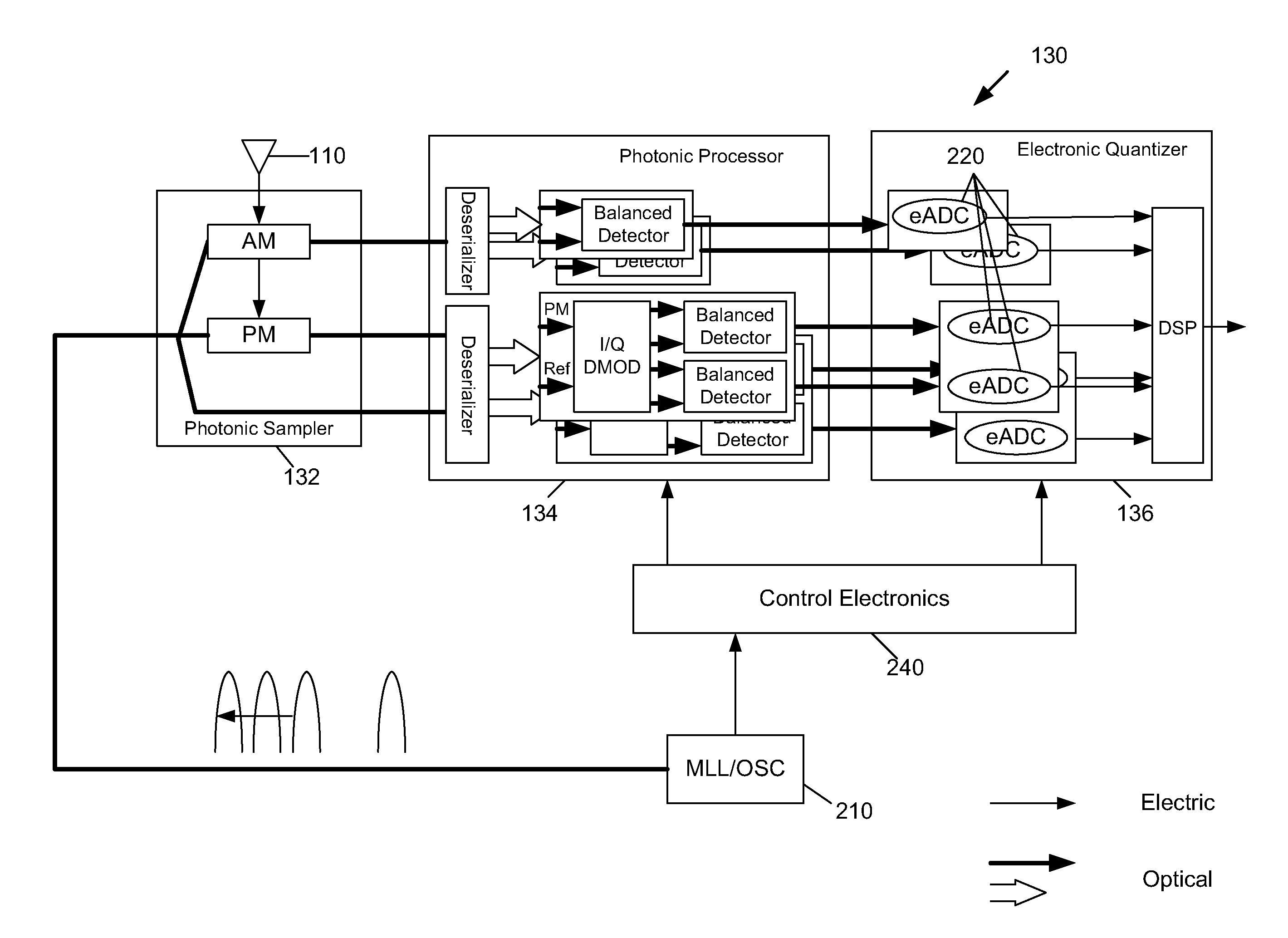
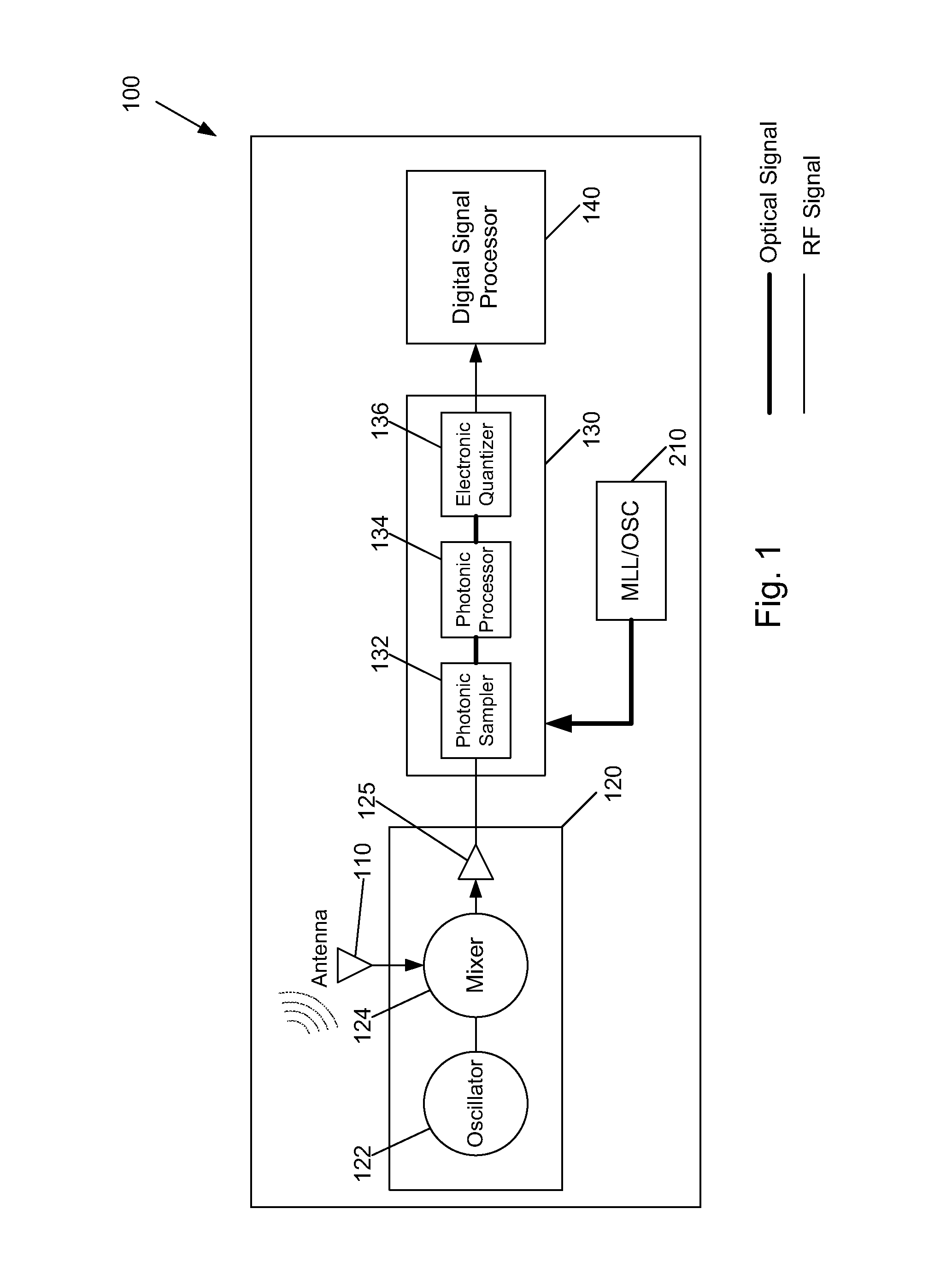
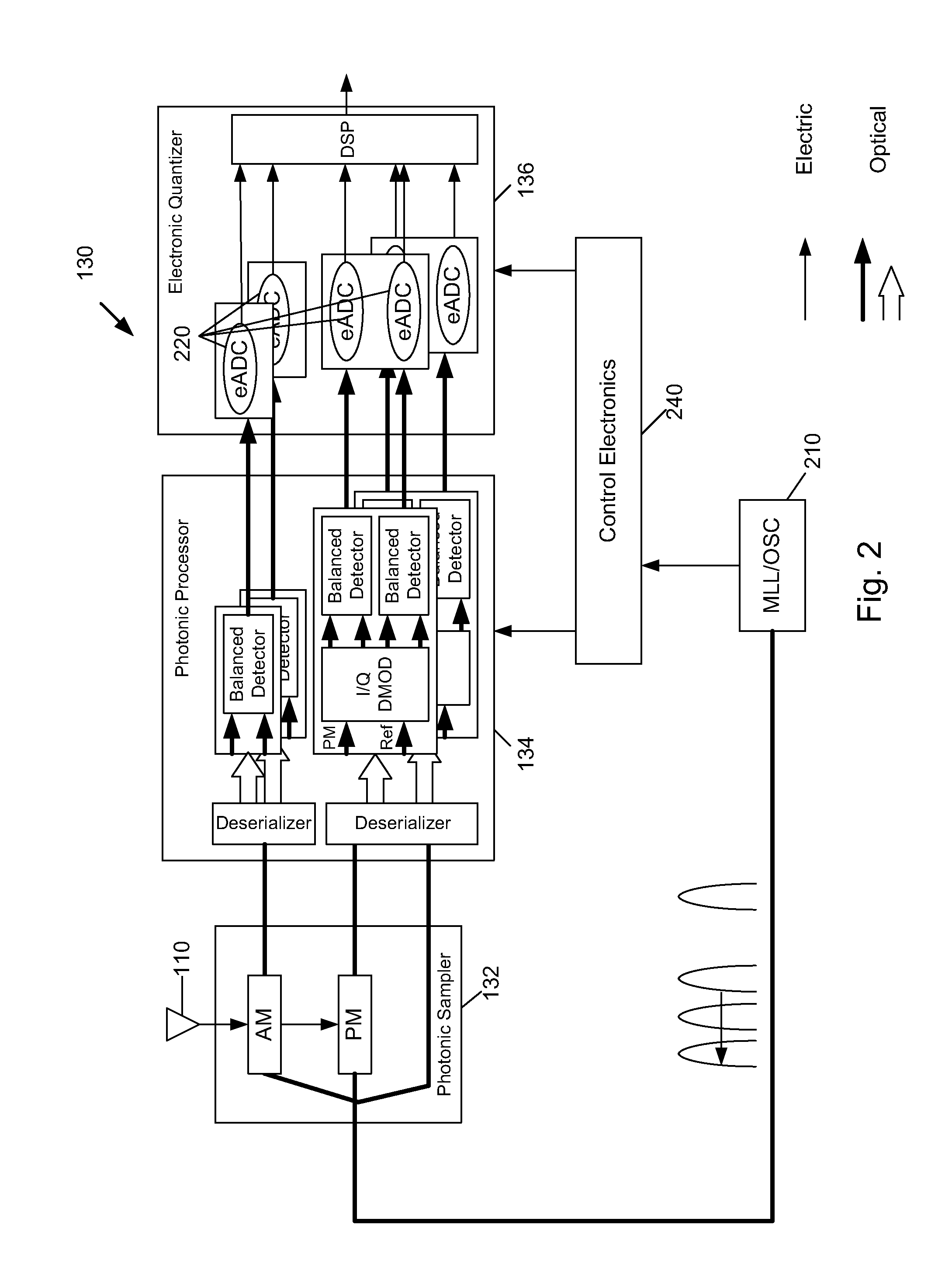
The patent describes a wide band RF receiver that uses a photonic Analog-to-Digital Converter (pADC) to convert an RF signal into an IF signal. The pADC then processes the signal using a photonic processor and an electronic quantizer to obtain phase-encoded and amplitude-encoded optical pulses. The receiver then uses the processed optical pulses to produce an RF signal. The technical effects of this invention include wider frequency range coverage, improved signal-to-noise ratio, and reduced interference between signals. A computer program product is also provided for easier reading and use of the patent.

Problems solved by technology

Fundamental performance limits of conventional electronic ADCs (eADCs) significantly constrain the potential of these systems, such as systems operating wide band in excess of several GHz.
Conventional eADCs do not have sufficient bandwidth without breaking up the bandwidth range into smaller channels or having to scan the range with a narrow band radio receiver.

Method used


Image

  • Wide band digital receiver: system and method
  • Wide band digital receiver: system and method
  • Wide band digital receiver: system and method

Examples


first embodiment

[0034]FIG. 4 is a plot that shows the role of the magnitude of phase shift induced by the microwave sampler utilized in the pADC 130 of a wide band receiver 100 of the first embodiment, in which the x-axis indicates the total number of 2π phase rotations induced by a full scale RF input signal, and in which it is assumed that each eADC is capable of 6.0 ENOB. As seen in the FIG. 4 plot, with the requirements of an MLL 210 as discussed above, two phase rotations are sufficient for 8 ENOB performance.

[0035]SFDR is another critical performance measure that typically is considered by persons of ordinary skill in the art for receiver applications. FIG. 5 is a plot that shows the results of a simulation of SFDR for a pADC 130 utilized in a wide band receiver 100 according to the first embodiment as a function of the number of phase rotations, with the same assumptions for eADCs 220 as mentioned above. In the simulation that was performed to obtain the FIG. 5 plot, SFDR was limited by the ...

fourth embodiment

[0049]FIG. 12 shows a Wide band RF tree architecture 1200 according to the invention, whereby the optical switches 620 are arranged in a tree configuration.

fifth embodiment

[0050]FIG. 13 shows a Wide band RF pipeline architecture 1300 according to the invention, whereby photonic processors 1310 are arranged in a pipeline configuration. While FIG. 13 is shown with respect to two-channel photonic processors 1310, three-channel photonic processors can alternatively be arranged in a pipeline configuration.


PUM


Abstract

A wide band digital RF receiver includes an RF front end configured to convert a RF signal into an IF signal. A wide band digital receiver also includes a photonic Analog-to-Digital Converter (pADC), and a digital processor. The pADC includes a photonic sampler that phase-encodes a stream of optical pulses with the IF signal to obtain phase-encoded optical pulses, and that amplitude-encodes an identical stream of optical pulses with the IF signal to obtain amplitude-encoded optical pulses. The pADC also includes a photonic processor and an electronic quantizer. The photonic processor processes the phase-encoded optical pulses by way of an I channel and a Q channel, and processes the amplitude-encoded optical pulses by way of an amplitude channel.

Description

FIELD OF THE INVENTION[0001]The present specification relates to a wide band radio frequency (RF) receiver More particularly, the present specification relates to a wide band receiver that includes a photonic analog-to-digital converter (ADC).[0002]RF system designers have long been aware that wide bandwidth, high resolution ADCs enable capabilities such as wide band receivers, flexible software defined radio system architectures, and digital radar. Fundamental performance limits of conventional electronic ADCs (eADCs) significantly constrain the potential of these systems, such as systems operating wide band in excess of several GHz. Conventional eADCs do not have sufficient bandwidth without breaking up the bandwidth range into smaller channels or having to scan the range with a narrow band radio receiver.[0003]Therefore, there is a need for a wide band digitizer that includes eADCs and has good operating characteristics (e.g, high resolution, large spur free dynamic range) with b...

Claims


Application Information

Patent Timeline
IPC IPC(8): H04B10/00
CPCH03M1/1245H04B2210/006
Inventor ZANONI, RAYMONDKING, OLIVER S.JEPSEN, KIM S.
Owner ROCKWELL COLLINS INC
Learn More