
Ray image modeling for fast catadioptric light field rendering

a catadioptric light field and image modeling technology, applied in the field of catadioptric cameras, can solve the problems of inability to find the correct correspondence, inability to match the correspondence, and inability to achieve the correct corresponden

Inactive Publication Date: 2013-04-30
SEIKO EPSON CORP
View PDF5 Cites 8 Cited by
  • Summary
  • Abstract
  • Description
  • Claims
  • Application Information

AI Technical Summary

Problems solved by technology

This approach, however, is very computer and labor intensive.
Indeed, reconstruction of 3D scenes from multiple 2D views is probably one of the most explored problems in computer vision.
Thus, correspondence matching is an essential problem in computer vision, especially in stereo vision, view synthesis, and 3D (or perspective) reconstruction.
Thus, automatically finding correspondence between pairs of images is the classic problem of stereo vision, but unfortunately the available algorithms to achieve this task may not always find the correct correspondences.
Thus, capturing a light field photographically requires many images from various view angles and intricate setups.
This often complicates the creation of light fields, especially for everyday use.
However, the use of light fields is complicated by their need for a plurality of digital images of a 3D subject taken from various view angles.
This makes catadioptric cameras systems ill-suited for the above-described methods of generating 3D images.
One may attempt applying pinhole model methods directly, as described above, to catadioptric cameras, but the results will have inherent errors, tend to exhibit distortions and not be optimal.

Method used


Image

  • Ray image modeling for fast catadioptric light field rendering
  • Ray image modeling for fast catadioptric light field rendering
  • Ray image modeling for fast catadioptric light field rendering

Examples


Embodiment Construction

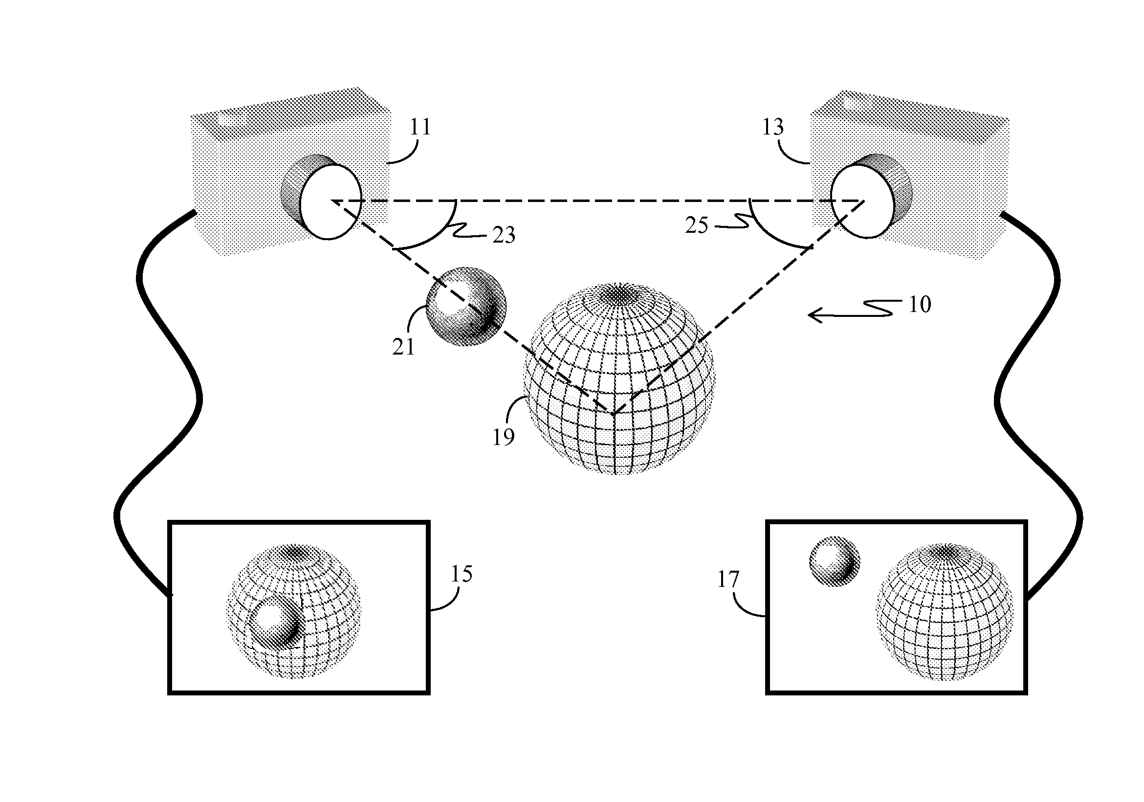
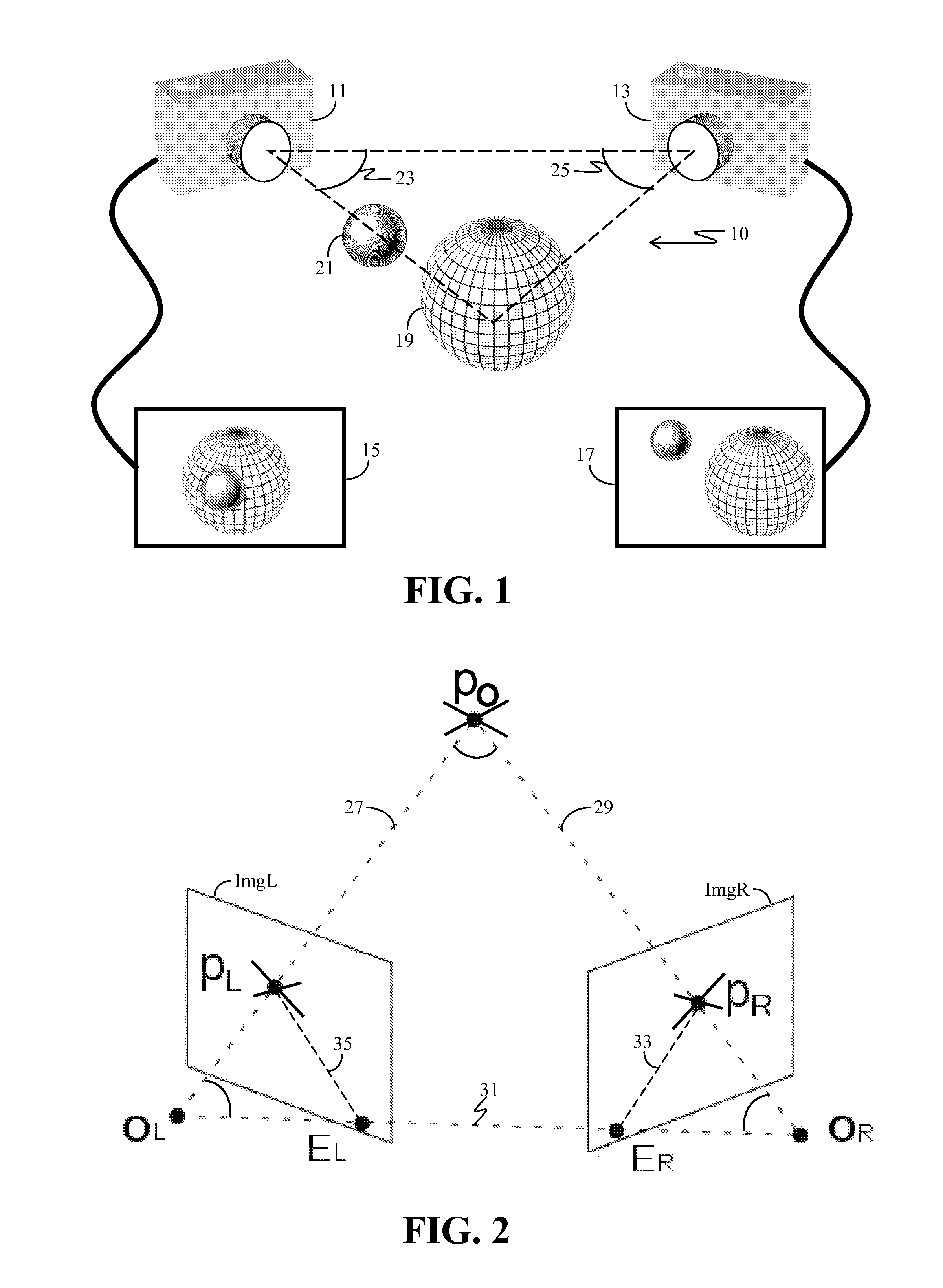
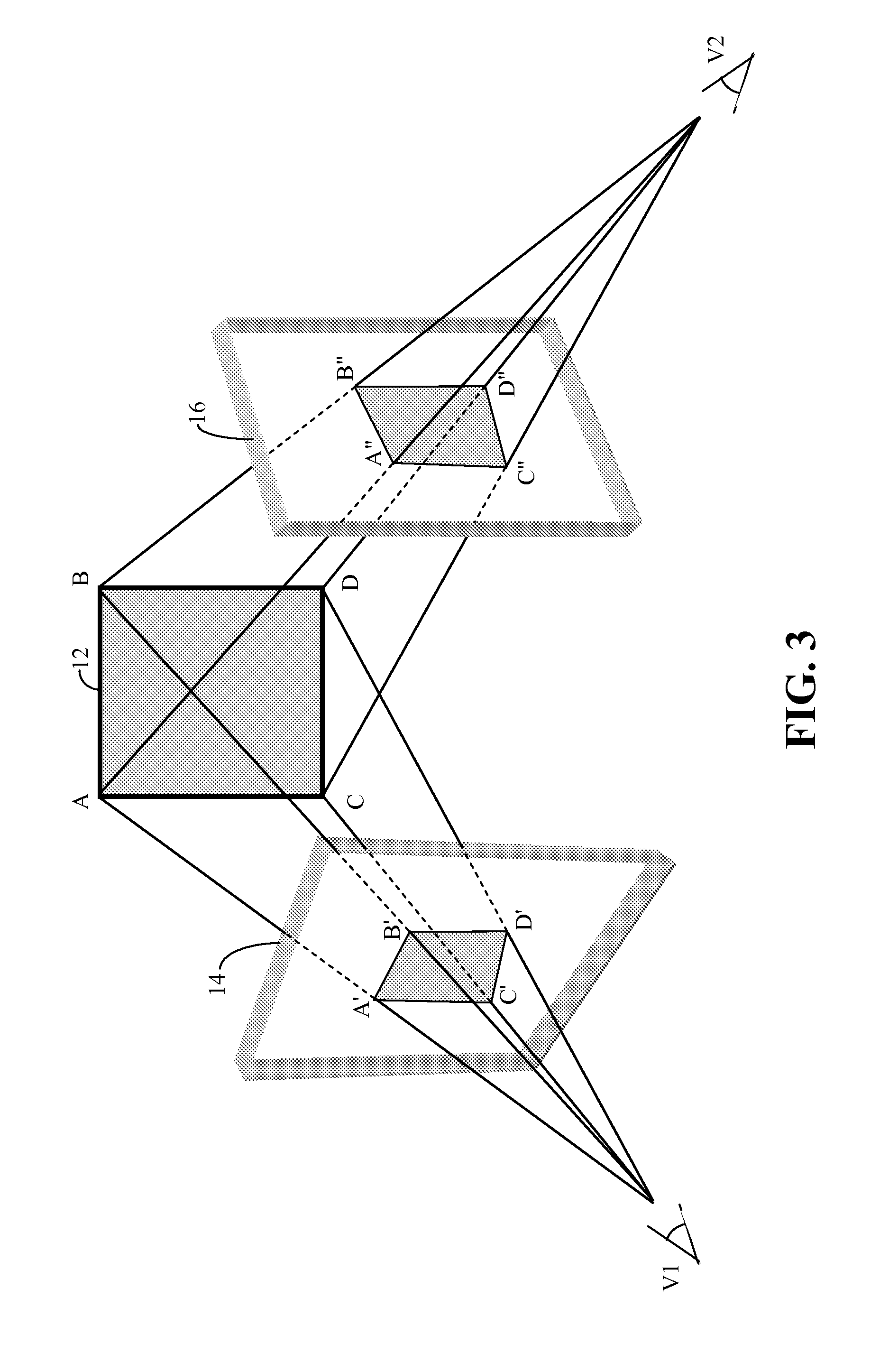
[0080]Correspondence matching is an essential problem in computer vision, especially in stereo, view synthesis, and 3D reconstruction. Indeed, stereo matching is probably the most studied 3D scene reconstruction method in computer vision. Most existing approaches assume that the input cameras are perspective cameras, which provide a single, comparatively narrow perspective view. And since use of perspective cameras, which are defined by the pinhole camera model, is typically assumed, most research efforts have focused on handling issues unrelated to different camera models. For example, most research has focused on textures, noise, specularity, and occlusion boundaries. These methods assume the existence of epipolar geometry, which permits two images to be rectified to have a pure horizontal parallax, and thus are subject to the stereo constraint.

[0081]Recently, interest in 3D reconstruction using multi-perspective cameras has been growing. Multi-perspective cameras provide a wider ...


PUM


Abstract

A catadioptric camera creates image light fields from a 3D scene by creating ray images defined as 2D arrays of ray-structure picture-elements (ray-xels). Each ray-xel captures light intensity, mirror-reflection location, and mirror-incident light ray direction. A 3D image is then rendered from the ray images by combining the corresponding ray-xels.

Description

BACKGROUND[0001]1. Field of Invention[0002]The present invention relates to the field of catadioptric cameras. More specifically, the present invention relate to the use of a catadioptric camera to capture a light field of a real-world scene.[0003]2. Description of Related Art[0004]Computer generated three dimensional, i.e. 3D, images are desirable in various applications, such as research and entertainment. There are various methods of rendering 3D images. For example, a scene consisting of geometric primitives composed of different materials and a set of lights may be input to a three-dimensional graphics system, which then computes and renders an output image based on this information. This approach, however, is very computer and labor intensive.[0005]An alternate approach, which may be termed image-based rendering, generates different, i.e. new, views of an environment based on a set of existing, pre-acquired images. This approach may be used to render 3D images from a collectio...

Claims


Application Information

Patent Timeline
Patent Type & Authority Patents(United States)
IPC IPC(8): H04N7/12
CPCG02B5/09G02B5/10H04N13/0217H04N13/0271G03B35/08H04N13/271H04N13/218
Inventor DING, YUANYUANXIAO, JING
Owner SEIKO EPSON CORP
Learn More