Device for the electric actuation of a safety-critical system
a technology for electrical actuation and safety-critical systems, which is applied in the direction of braking systems, welding electric supplies, resistance welding apparatuses, etc., can solve the problems of high technical cost, unidirectional current flow between the terminals, and the manufacture and installation of known devices entail high technical costs, so as to achieve safe and reliable determination and/or identification
- Summary
- Abstract
- Description
- Claims
- Application Information
AI Technical Summary
Benefits of technology
Problems solved by technology
Method used
Image
Examples
first embodiment
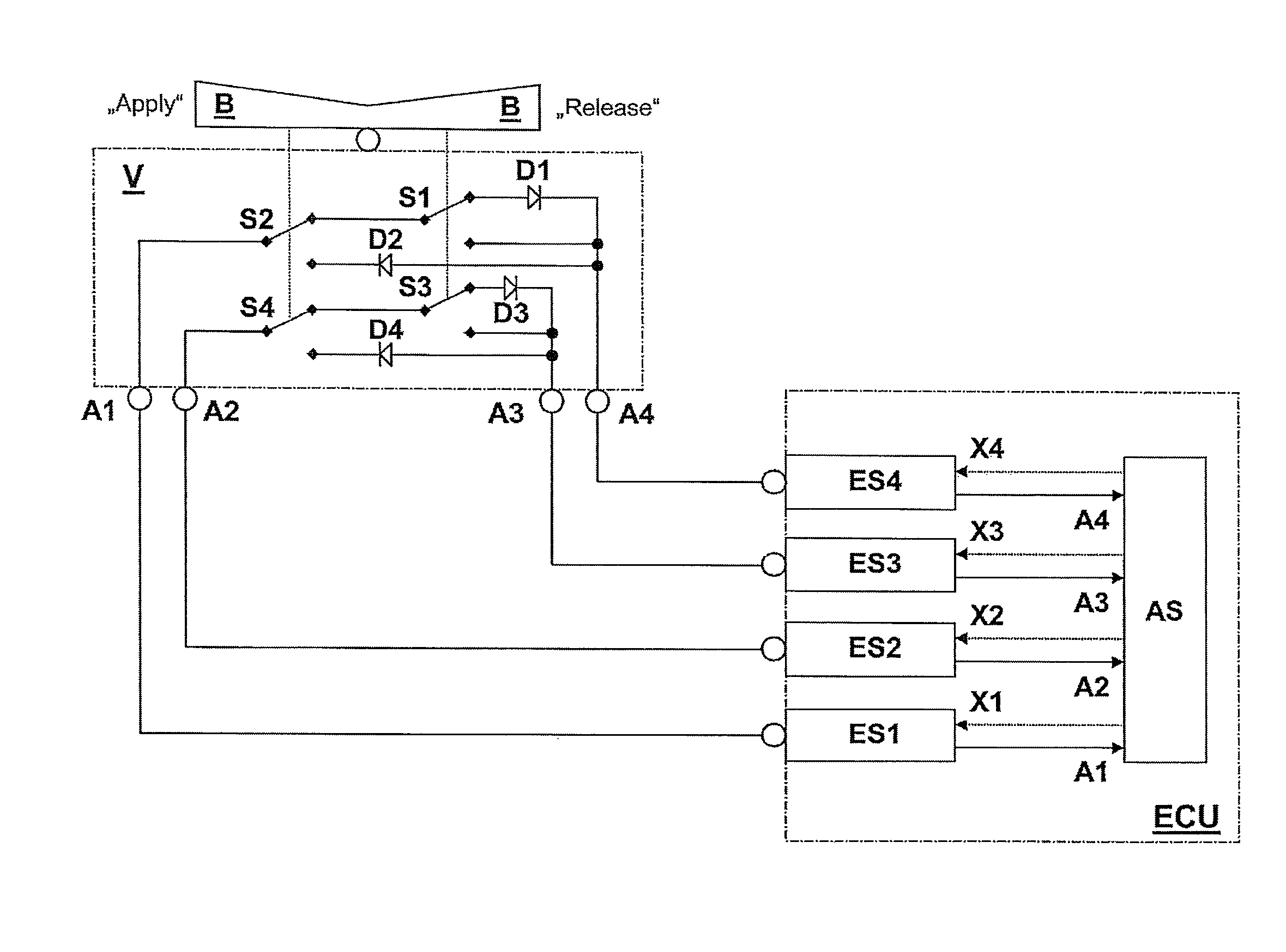
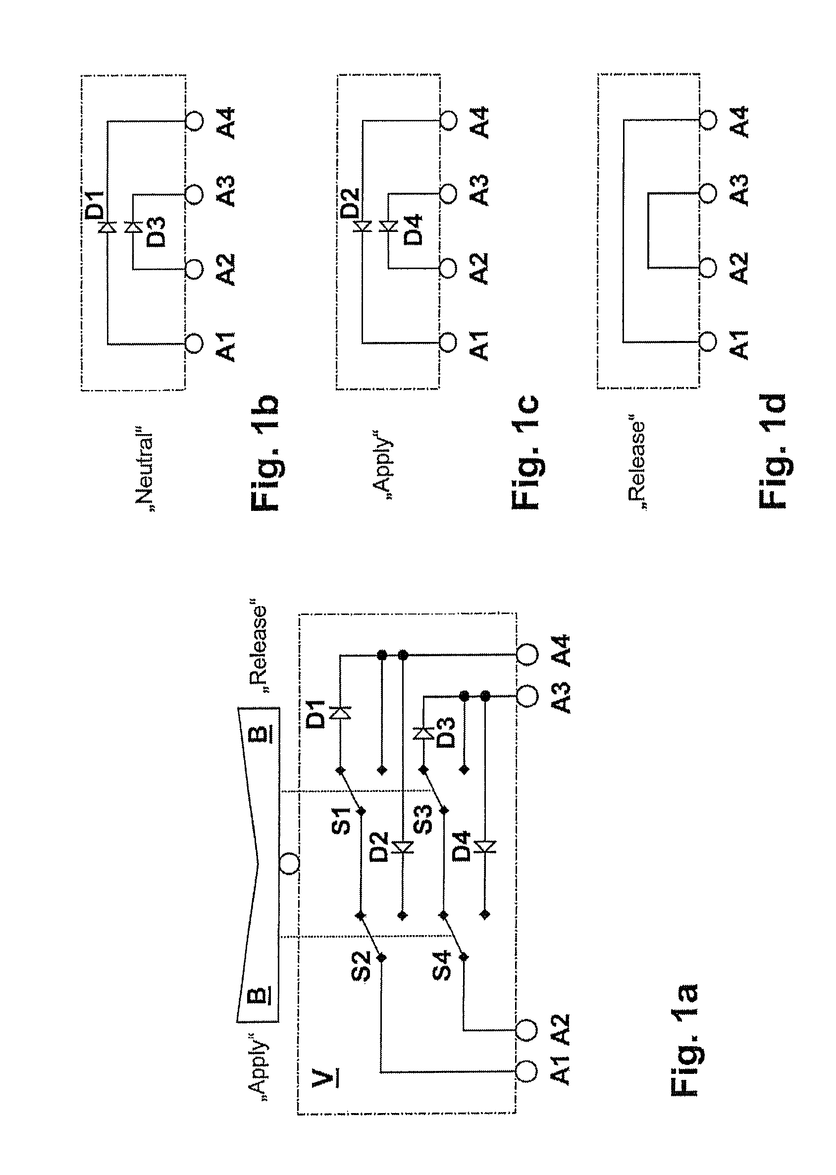
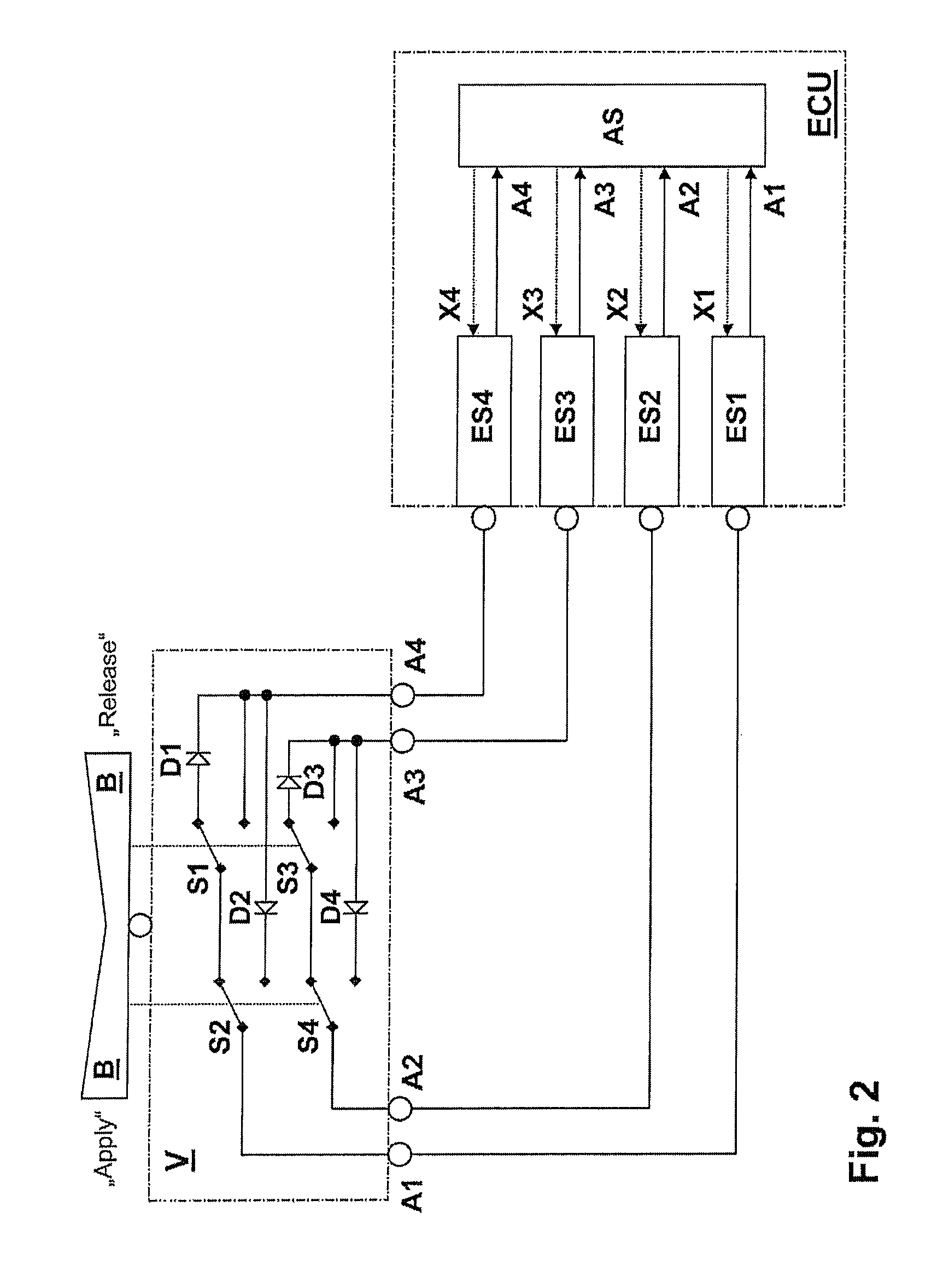
[0025]For a device V according to the invention for the electrical actuation of a safety-critical system according to FIG. 1a, first of all two terminals A1 and A4 are considered. For electrically connecting the terminals A1 and A4 two switches S1 and S2 are provided, which are connected in series and each have two switching positions. In order to determine the switching positions of the two switches S1 and S2, the two switches S1 and S2 are operationally coupled to an operator control element B, by means of which the following three operating states are selectable for the system:[0026](i.) For a first operating state the two switches S1 and S2 are situated, as represented in FIG. 1a, in their top switching position so that there is an electrical connection by means of a current direction element D1 (for example a diode), which allows a unidirectional current flow only in the direction from the terminal A1 to the terminal A4 and blocks a current flow in the direction from the termin...
second embodiment
[0047]FIG. 5a shows a device V according to the invention, for which at first three terminals A1, A3 and A4 are considered. For electrically connecting the terminals A1 and A4 and / or A3 two switches S1 and S2 are provided, which each have two switching positions. In order to determine the switching positions of the two switches S1 and S2, the two switches S1 and S2 are operationally coupled to an operator control element B, by means of which the following three operating states are selectable for the system:[0048](i.) For a first operating state the two switches S1 and S2 are situated, as represented in FIG. 5a, in their top switching position so that there is an electrical connection by means of a current direction element D1, which allows a unidirectional current flow only in the direction from the terminal A1 to the terminal A4 and blocks a current flow in the direction from the terminal A4 to the terminal A1.[0049](ii.) For a second operating state the switch S2 is situated in i...
third embodiment
[0057]FIG. 6a shows a device V according to the invention, for which at first two terminals A1 and A4 are considered. For electrically connecting the terminals A1 and A4 two switches S1 and S2 are provided, which each have two switching positions. In order to determine the switching positions of the two switches S1 and S2, the two switches S1 and S2 are operationally coupled to an operator control element B, by means of which the following three operating states are selectable for the system:[0058](i.) For a first operating state the two switches S1 and S2 are situated, as represented in FIG. 6a, in their top switching position so that there is an electrical connection by means of the current direction element D1, which allows a unidirectional current flow only in the direction from the terminal A4 to the terminal A1 and blocks a current flow in the direction from the terminal A1 to the terminal A4.[0059](ii.) For a second operating state the switch S2 is situated in its bottom swit...
PUM
| Property | Measurement | Unit |
|---|---|---|
| current | aaaaa | aaaaa |
| current flow | aaaaa | aaaaa |
| electrical | aaaaa | aaaaa |
Abstract
Description
Claims
Application Information
 - R&D
- Intellectual Property
- Life Sciences
- Materials
- Tech Scout
- Unparalleled Data Quality
- Higher Quality Content
- 60% Fewer Hallucinations
Browse by: Latest US Patents, China's latest patents, Technical Efficacy Thesaurus, Application Domain, Technology Topic, Popular Technical Reports.
© 2025 PatSnap. All rights reserved.Legal|Privacy policy|Modern Slavery Act Transparency Statement|Sitemap|About US| Contact US: help@patsnap.com


