


Quick Research
Generate reliable direction feasibility study reports for your R&D in just a few steps.

Technical Q&A
Discover and master advanced knowledge NOW. Basics, ideas, possibilities, all at once.

Find Solutions
As an expert in R&D theories, this can generate solutions to your technical problems instantly.

Evaluate Feasibility
Analyze your overall solution with one click, know your potential R&D risks in advance.

Monitor Landscape
Get weekly tech updates, stay abreast of the latest tech innovations and key insights.
Hose connection
a technology of hose connection and hose body, which is applied in the direction of hose connection, liquid handling, packaging goods type, etc., can solve the problems of increasing the potential stressing the assembly of each hose connection, and naturally increasing the risk of leakage between components, so as to reduce assembly time
- Summary
- Abstract
- Description
- Claims
- Application Information
AI Technical Summary
Benefits of technology
Problems solved by technology
Method used
Image


Examples
first embodiment
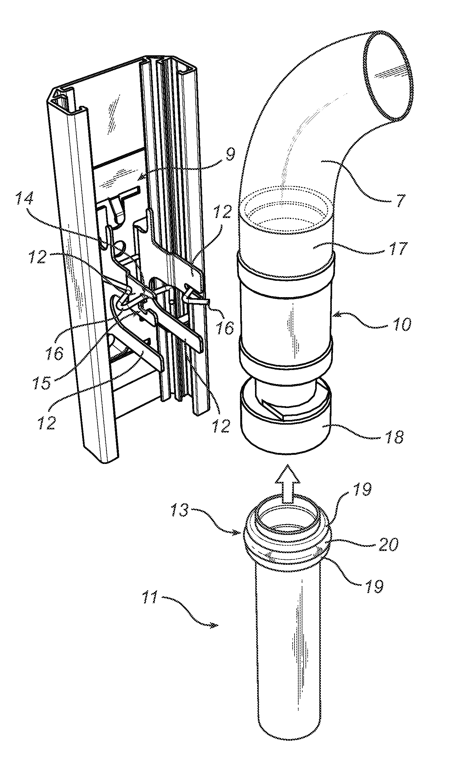
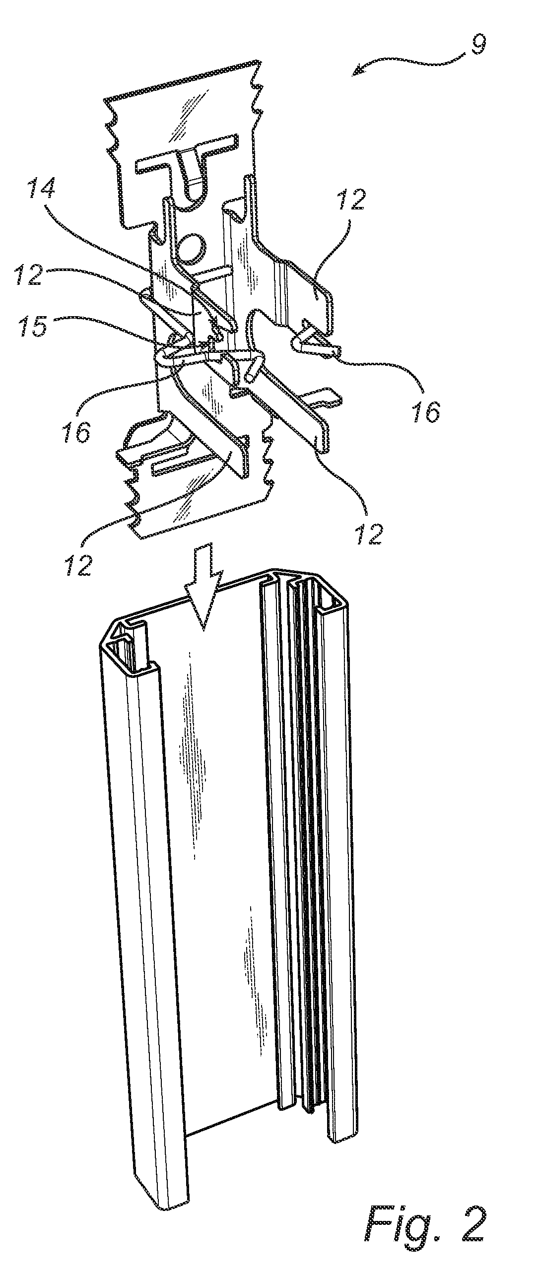
[0029]FIG. 2 and FIG. 3 illustrate the components included in a hose connection 8 according to the invention. The hose connection 8 comprises a locking device 9, a hose 7, an intermediate member 10 and a pipe 11. The locking device 9 is adapted to be fixed to the fuel dispensing unit 1 for example by means of screws, bolts, welds, etc. Further, the locking device 9 is adapted to interlock the intermediate member 10 and the pipe 11 as well as to secure the hose connection 8 to the fuel dispensing unit 1. The intermediate member 10 is adapted to connect the pipe 11 for transporting fuel from a fuel reservoir and the hose 7 for transporting fuel to a motor vehicle. The locking device 9 comprises at least one connector 12 protruding in a transverse direction in relation to the hose 7, which connector 12 is adapted to engage with the intermediate member 10 and an end portion 13 of the pipe 11 in order to interlock the intermediate member 10 and the pipe 11. The connector 12 of the lockin...
second embodiment
[0031]FIG. 5 illustrates a hose connection 8 according to the present invention. The intermediate member 10 comprises two ports. A vapor recovery pipe 21 is connected to each one of the two ports. The end portions of the vapor recovery pipes 21 are provided with two annular beads which accommodate an O-ring between them. The end portions of the vapor recovery pipes 21 are provided in a receiving portion of the ports of the intermediate member 10. Naturally, the vapor recovery pipes 21 can be connected to the ports of the intermediate member 10 in other ways, such as by means of screwing, bolting, welding, etc. A fastening device 22 is provided on the intermediate member 10 securing the vapor recovery pipes 21 in relation to the intermediate member 10. The fastening device 22 comprises a slot 23 on each side so that the vapor recovery pipes 21 can be attached to and detached from the intermediate member 10, respectively. The hose 7 is coaxial in order to separate fuel and vapor.
[0032...
PUM
| Property | Measurement | Unit |
|---|---|---|
| resilient | aaaaa | aaaaa |
| time | aaaaa | aaaaa |
Abstract
Description
Claims
Application Information
 - R&D Engineer
- R&D Manager
- IP Professional
- Industry Leading Data Capabilities
- Powerful AI technology
- Patent DNA Extraction
Browse by: Latest US Patents, China's latest patents, Technical Efficacy Thesaurus, Application Domain, Technology Topic, Popular Technical Reports.
© 2024 PatSnap. All rights reserved.Legal|Privacy policy|Modern Slavery Act Transparency Statement|Sitemap|About US| Contact US: help@patsnap.com