
Blower assembly with integral injection molded suspension mount

a technology of injection molding and blower assembly, which is applied in the direction of positive displacement liquid engine, piston pump, liquid fuel engine, etc., can solve the problems of not being able to achieve the required compressive flow at a high efficiency level, the configuration of the radial fan wheel as used in the muller reference is not understood to possess the ability to reduce noise, and the miniature fan as used in the muller reference is not understood to operate at a reduced noise level. , to achieve th

Active Publication Date: 2013-04-23
VYAIRE MEDICAL 211 INC
View PDF27 Cites 8 Cited by
  • Summary
  • Abstract
  • Description
  • Claims
  • Application Information

AI Technical Summary

Benefits of technology

The patent describes a blower assembly that minimizes aerodynamic losses by optimizing the vane height and positioning close to the housing interior surface. It also maintains a small air gap to prevent leakage between the vanes. The impeller is balanced to minimize vibration and the bearing assembly is removably mountable to stator bore for easy replacement. The blower assembly has different flow characteristics due to different cross-sections and vane heights, resulting in improved performance.

Problems solved by technology

Although the miniature fan of the Muller reference is disclosed as having a relatively small size of about 23 mm in height and 73 mm in width, the miniature fan is not believed to be suitable for certain applications such as in a CPAP device which requires an even smaller size and lower-weight blower assembly.
Furthermore, the configuration of the radial fan wheel as used in the Muller reference is not understood to possess the ability to produce the required compressive flow at a high efficiency level.
Furthermore, the miniature fan as used in the Muller reference is not understood to operate at a reduced noise level and with reduced vibration output as is required in a portable CPAP device.
Unfortunately, the blades in the fan of the Kudo reference form a relatively large air gap with the housing such that, during operation, the fan is believed to generate fluid eddies as a result of air flowing between the air gap.
The fluid eddies are believed to interfere with the aerodynamic efficiency of the compressed air flowing through the vanes toward the outlet.
In addition, the reduced aerodynamic efficiency of the fan is believed to result in a concomitant increase in noise such that the Kudo device is also not believed to be suitable for use in a portable CPAP device.

Method used


Image

  • Blower assembly with integral injection molded suspension mount
  • Blower assembly with integral injection molded suspension mount
  • Blower assembly with integral injection molded suspension mount

Examples


Embodiment Construction

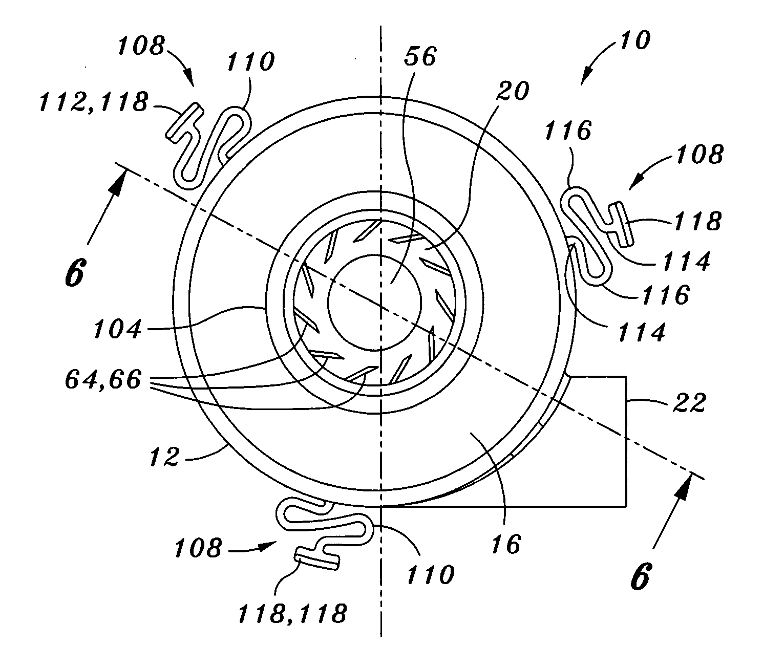
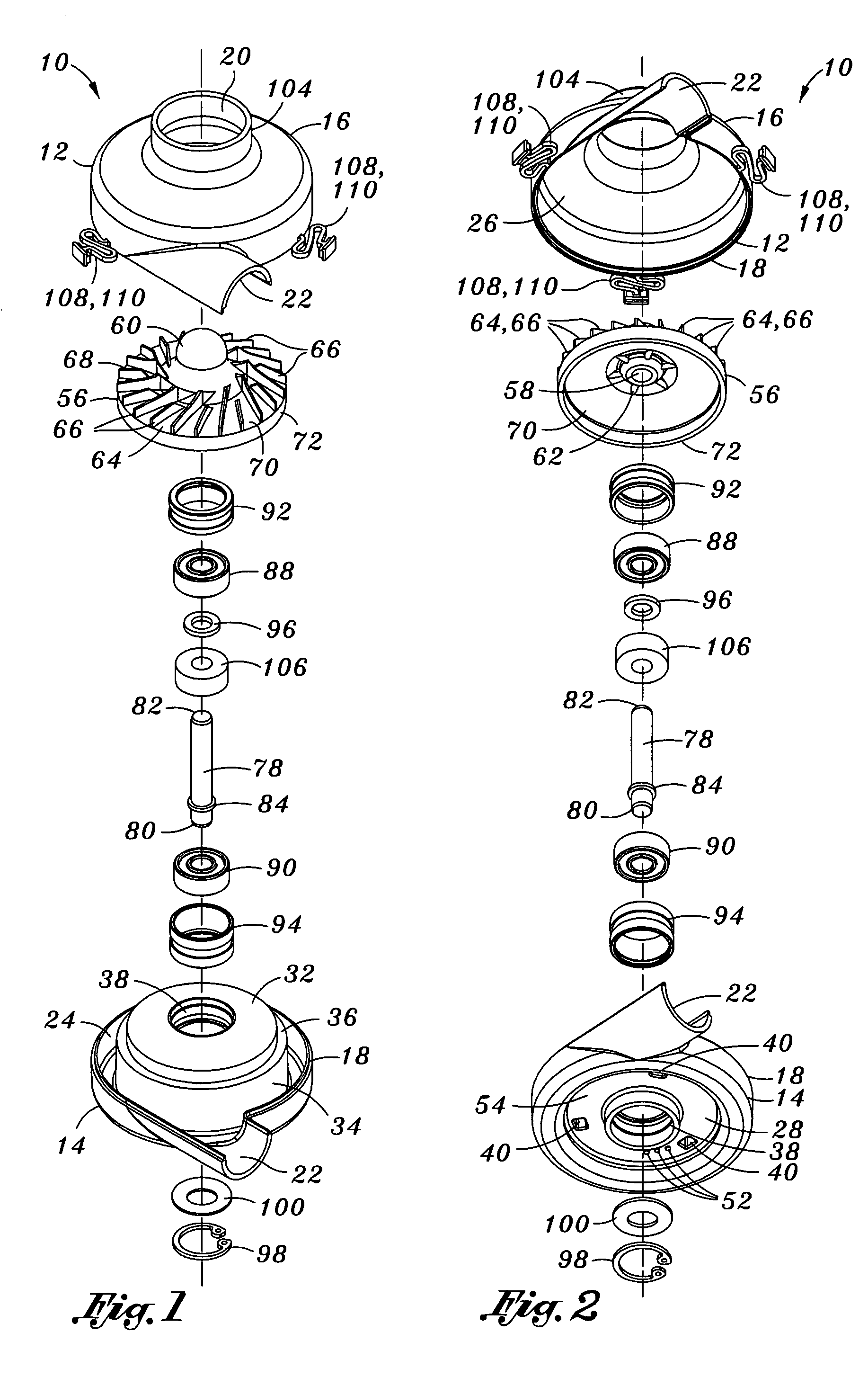
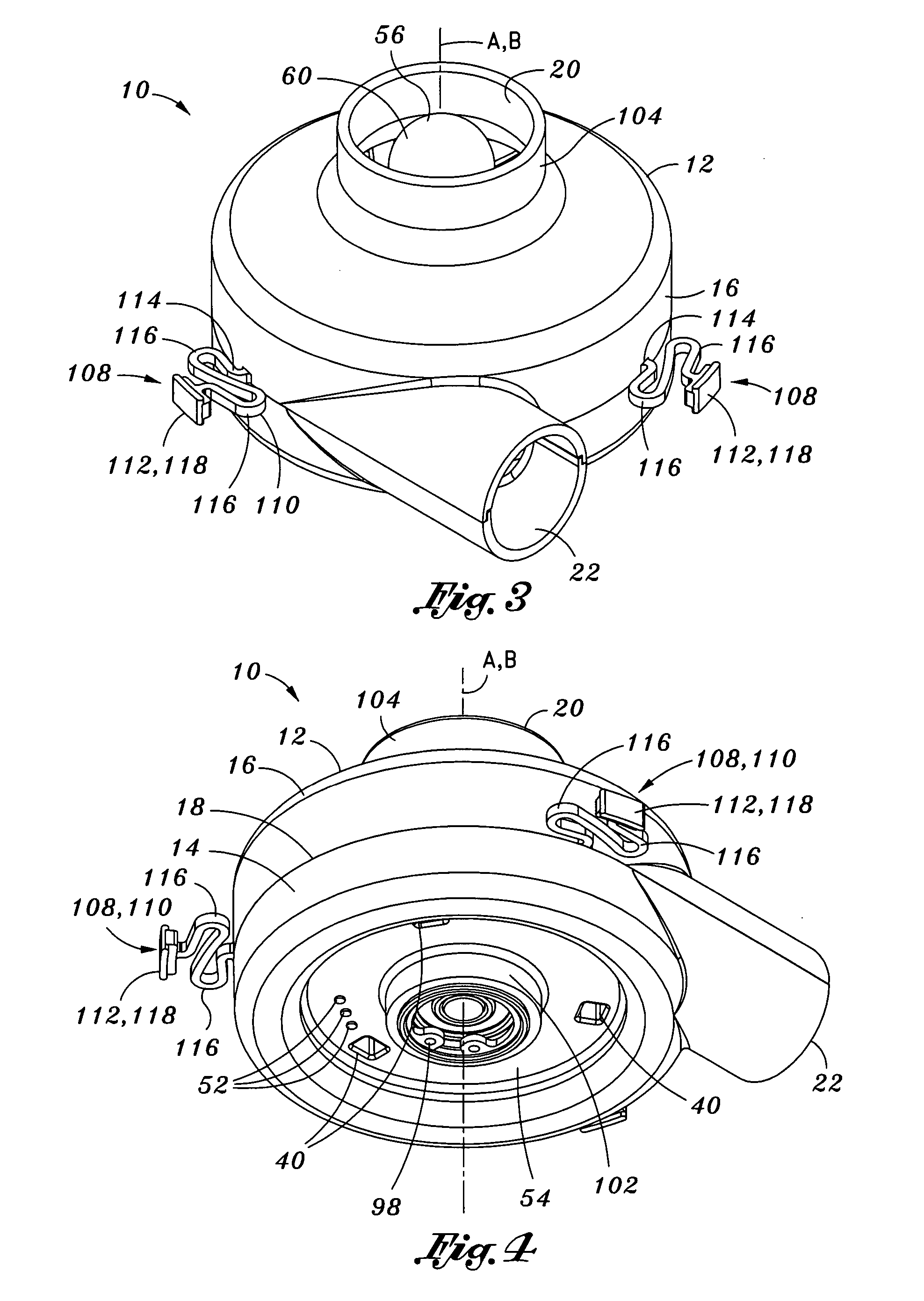
[0036]Referring now to the drawings wherein the showings are for purposes of illustrating preferred embodiments of the present invention and not for purposes of limiting the same, shown in FIGS. 1-10 is a blower assembly 10 which is specifically configured to provide a relatively high flow rate at relatively high pressure while consuming relatively little input power. The blower assembly 10 is configured in a relatively small size having a short axial height small diameter but which is capable of producing a relatively high flow rate of compressed with minimal output of vibration, noise and heat. In this regard, the blower assembly 10 is particularly well-suited for use in sensitive applications such as in a portable or wearable continuous positive airway pressure (CPAP) device similar to that which is disclosed in U.S. application Ser. No. 11 / 649,674 entitled User Interface and Headgear for a Continuous Positive Airway Pressure Device, the entire contents of which is incorporated b...


PUM


Abstract

A blower assembly comprises a blower housing having a stator assembly integrally formed therewith. The stator assembly includes a stator bore having a rotor magnet rotatable therewithin such that the motor assembly is configured as a brushless D.C. motor. An impeller is mounted on a motor shaft of the motor assembly and has a plurality of vanes extending upwardly therefrom. Each one of the vanes has a vane height which is optimized to minimize the formation of fluid eddy losses during compression of air by the impeller. A bearing assembly rotatably coupling the rotor magnet to the stator assembly is sized and configured to maintain an air gap of approximately 0.0002 inches between the vanes and a housing interior surface of the blower housing during rotation of the impeller.

Description

CROSS-REFERENCE TO RELATED APPLICATIONS[0001]The present application claims priority to U.S. Provisional Application No. 60 / 793,433 filed on Apr. 20, 2006, the entire contents of which is expressly incorporated by reference herein. The present application is also related to U.S. Utility patent application Ser. No. 11 / 128,552 entitled PORTABLE CONTINUOUS POSITIVE AIRWAY PRESSURE SYSTEM filed on May 13, 2005, and to U.S. Utility patent application Ser. No. 11 / 649,674 entitled USER INTERFACE AND HEAD GEAR FOR A CONTINUOUS POSITIVE AIRWAY PRESSURE DEVICE filed on Jan. 4, 2007, the entire contents of each being expressly incorporated by reference herein.STATEMENT RE: FEDERALLY SPONSORED RESEARCH / DEVELOPMENT[0002](Not Applicable)BACKGROUND[0003]The present invention relates generally to patient ventilation systems and, more particularly, to a motor blower assembly incorporating an improved brushless D.C. motor assembly of reduced size and which is configured to rotatably drive a precision...

Claims


Application Information

Patent Timeline
Patent Type & Authority Patents(United States)
IPC IPC(8): H02K5/24F04B35/04
CPCF04D25/0606H02K5/24H02K7/14A61M16/0066H02K5/1732A61M2205/42F04D29/668
Inventor HOFFMAN, LESLIELATHROP, RAYMOND
Owner VYAIRE MEDICAL 211 INC
Learn More