
Infant swing

a technology for swinging and infants, applied in the field of infant swinging, can solve the problems of reducing the flexibility of infant swinging in structural design, affecting the original layout of the other components in the driving hub, and requiring additional space for the power supply devi

Active Publication Date: 2013-04-16
WONDERLAND SWITZERLAND AG
View PDF17 Cites 7 Cited by
  • Summary
  • Abstract
  • Description
  • Claims
  • Application Information

AI Technical Summary

Benefits of technology

The present invention provides an infant swing that can be easily moved and balanced using a carrier and a swing arm. The swing has a mechanism to prevent the foot from rotating and a power supply to drive the arm. The technical effects of this invention are improved stability and safety for swimming and swinging, as well as easier movement and reduced fatigue for the user.

Problems solved by technology

For disposal of the power supply device in the driving hub, since there are often other related driving components (e.g. a motor) installed in the driving hub, an additional space will be required for the power supply device and the original layout of the other components in the driving hub will be therefore affected.
Accordingly, the said design may not only reduce flexibility of the infant swing in structural design, but also increase the volume of the driving hub occupied on the infant swing so as to affect the look of the infant swing.

Method used


Image

  • Infant swing
  • Infant swing
  • Infant swing

Examples


Embodiment Construction

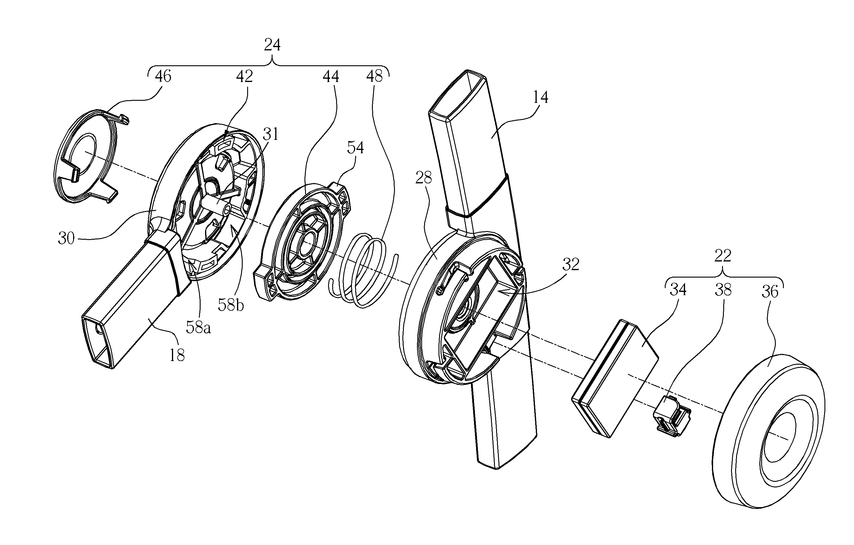
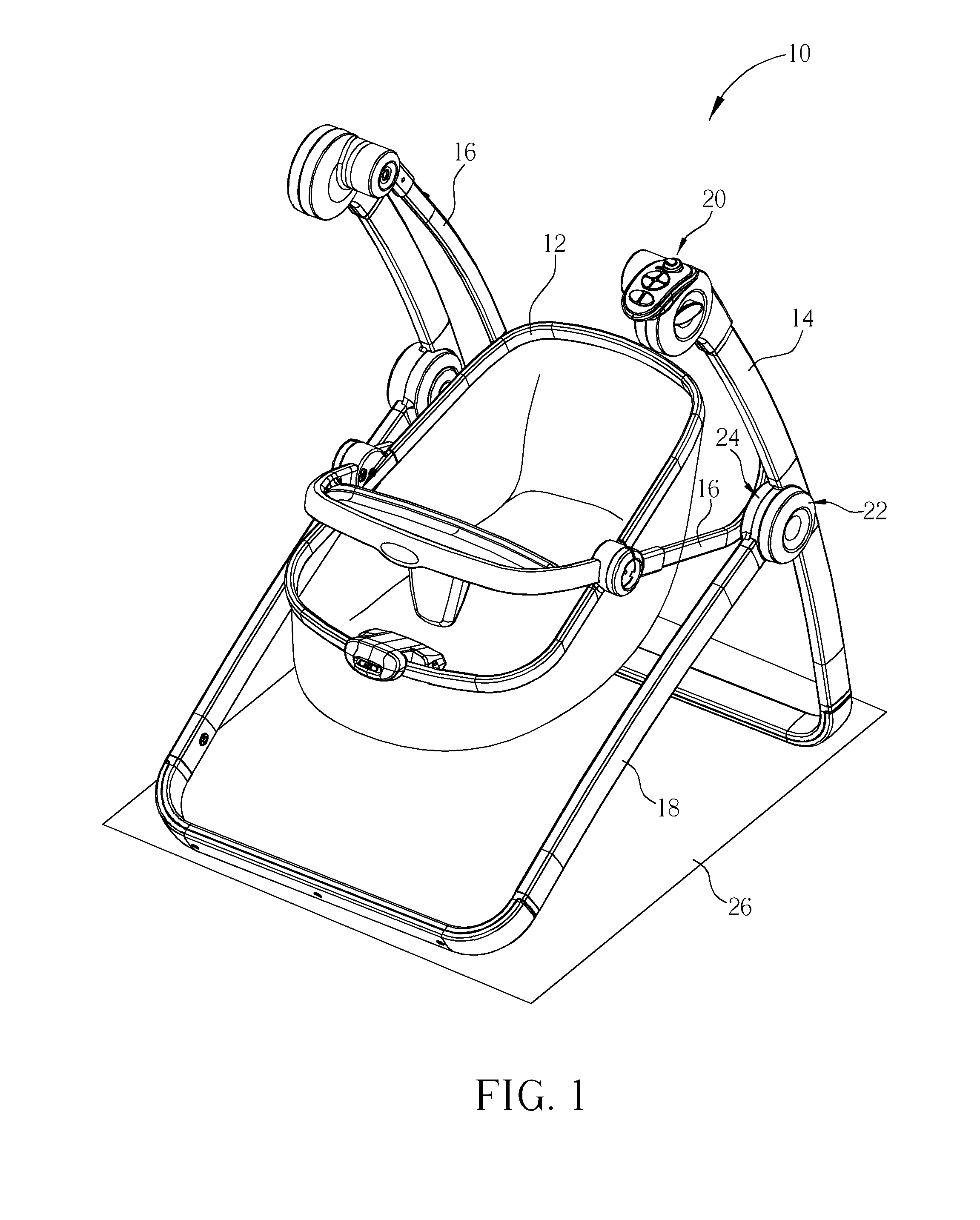
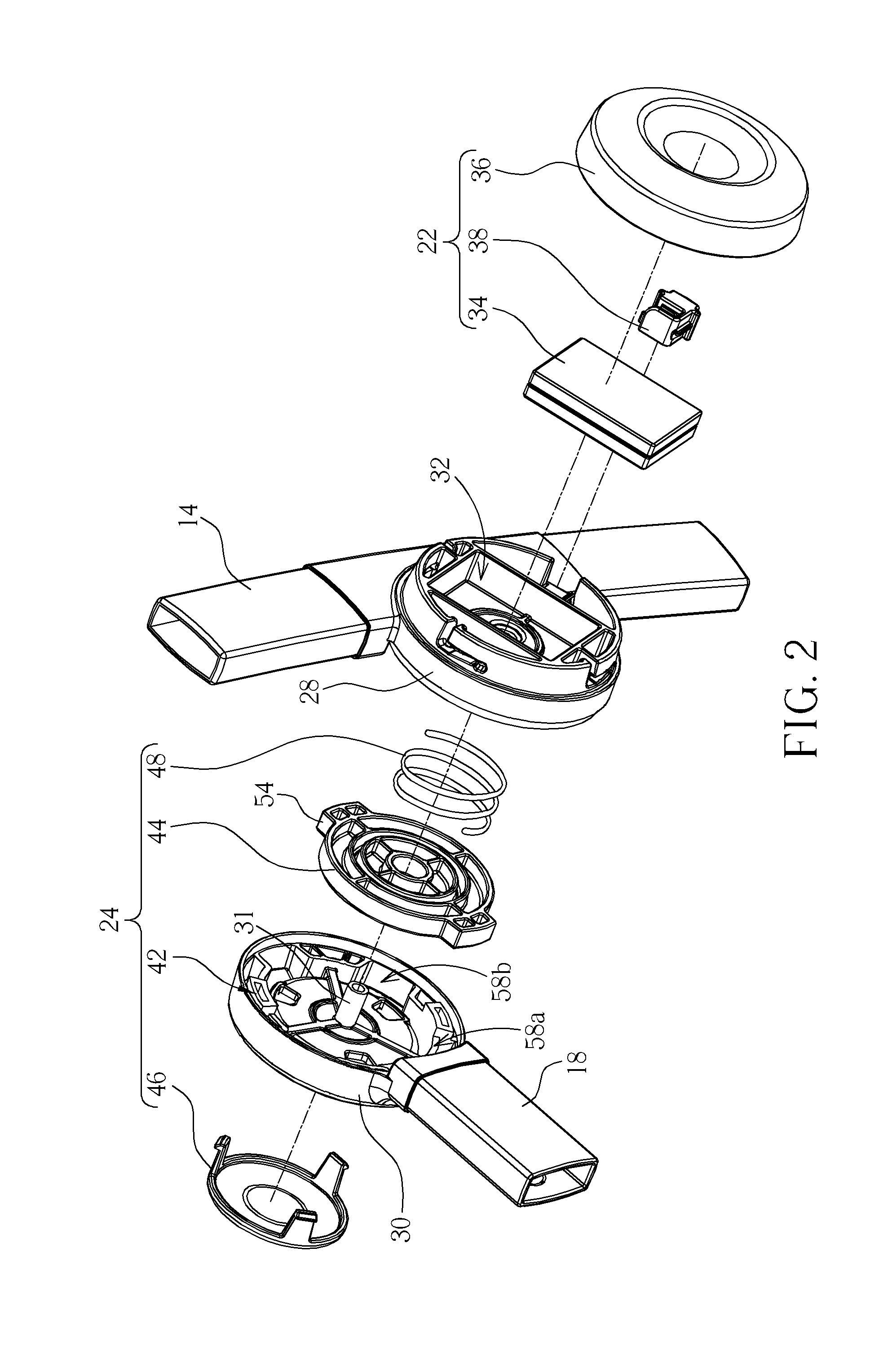
[0016]Please refer to FIG. 1, which is a schematic diagram of an infant swing 10 according to a preferred embodiment of the present invention. As shown in FIG. 1, the infant swing 10 includes a carrier 12, a first foot 14, at least one arm 16 (two shown in FIG. 1), a second foot 18, a driving device 20, a power supply device 22, and a pivotal positioning mechanism 24. The carrier 12 is used for holding an infant and is preferably an infant cradle for lying or a seat for sitting thereon. The arm 16 is connected to the first foot 14 and the carrier 12. The second foot 18 is pivotally connected to the first foot 14 for supporting the carrier 12 above a supporting surface 26 cooperatively with the first foot 14 and the arm 16. The supporting surface 26 can be a common residence surface for disposal of the infant swing 10, such as a floor and so on. The driving device 20 is disposed on a top portion of the first foot 14 and connected to the arm 16. The driving device 20 is used for drivi...


PUM


Abstract

An infant swing includes a carrier, a first foot, at least one arm, a second foot, a pivotal positioning mechanism, a driving device, and a power supply device. The arm is connected to the first foot and the carrier. A second pivot base of the second foot is pivotally connected to a first pivot base of the first foot. The second foot is used for supporting the carrier above a supporting surface cooperatively with the first foot and the arm. The pivotal positioning mechanism is disposed between the first pivot base and the second pivot base. The pivotal positioning mechanism is used for constraining rotation of the second foot. The driving device is used for driving the arm. The power supply device is used for providing electric power to the driving device so as to make the carrier capable of swinging relative to the first foot.

Description

BACKGROUND OF THE INVENTION[0001]1. Field of the Invention[0002]The present invention relates to an infant swing, and more particularly, to an infant swing for integrating a power supply device onto a foot.[0003]2. Description of the Prior Art[0004]A conventional infant swing is often equipped with a power supply device for performing functions of music, swing, and so on. A common method for disposing a power supply device on an infant swing involves disposing the power supply device on a support foot or in a driving hub which is used for driving the infant swing to swing.[0005]For disposal of the power supply device in the driving hub, since there are often other related driving components (e.g. a motor) installed in the driving hub, an additional space will be required for the power supply device and the original layout of the other components in the driving hub will be therefore affected. Accordingly, the said design may not only reduce flexibility of the infant swing in structur...

Claims


Application Information

Patent Timeline
Patent Type & Authority Patents(United States)
IPC IPC(8): A63G9/16A63G9/00
CPCA47D13/105A47D9/057A47D9/005A47D13/101
Inventor ZHANG, XIAO-JIAN
Owner WONDERLAND SWITZERLAND AG
Learn More