
Clip applier and methods of use

a technology which is applied in the field of applicator and clip, can solve the problems of time-consuming and expensive procedures, requiring as much as an hour of physician's or nurse's time, and uncomfortable for patients, and achieves the effect of facilitating hemostasis

Inactive Publication Date: 2013-03-19
INTEGRATED VASCULAR SYST
View PDF953 Cites 26 Cited by
  • Summary
  • Abstract
  • Description
  • Claims
  • Application Information

AI Technical Summary

Benefits of technology

The present invention relates to a clip applier apparatus for delivering a closure element to an opening formed in a wall of a body lumen or body tissue. The clip applier includes a carrier tube with an outer surface retaining the closure element in a substantially tubular configuration. The carrier tube has slits at a distal end and can split at the slits to form outwardly bendable carrier flaps. The clip can be a shape-memory clip with a relaxed configuration and a substantially planar-annular body. The clip can be oriented and held in a retaining configuration with an asymmetrically-elongated tubular shape and a body portion with tines directed inwardly from the body. The clip can retract to a deploying configuration with a symmetrical tubular shape and tines evenly spaced. The clip can automatically retract from the retaining configuration to the deploying configuration when released from the clip applier. The clip applier can include a cover tube that retains the clip in the retaining configuration and can retain the clip expander in a contracted orientation so that the clip expander can expand when moved distally past the distal end of the cover tube. The technical effects of the invention include improved closure of body openings and reduced risk of complications during the procedure.

Problems solved by technology

This procedure, however, may be time consuming and expensive, requiring as much as an hour of a physician's or nurse's time.
It is also uncomfortable for the patient, and requires that the patient remain immobilized in the operating room, catheter lab, or holding area.
In addition, a risk of hematoma exists from bleeding before hemostasis occurs.
This device, however, requires that an anchor of the plug be positioned within the vessel, and therefore, may increase the risk of over-advancement of the plug itself into the vessel.

Method used


Image

  • Clip applier and methods of use
  • Clip applier and methods of use
  • Clip applier and methods of use

Examples


Embodiment Construction

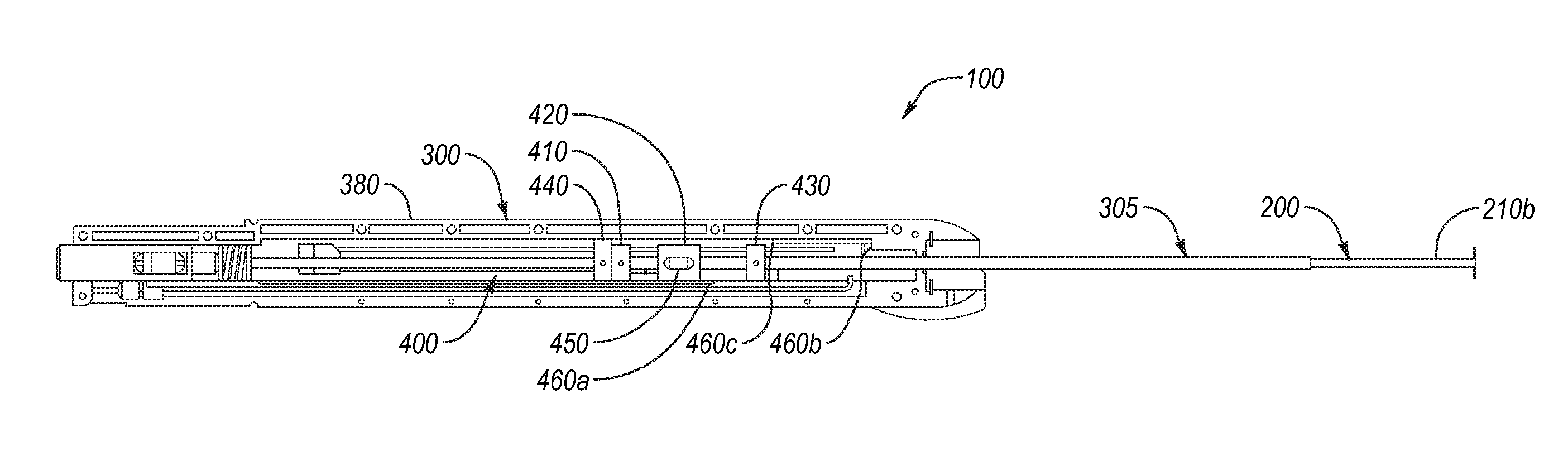
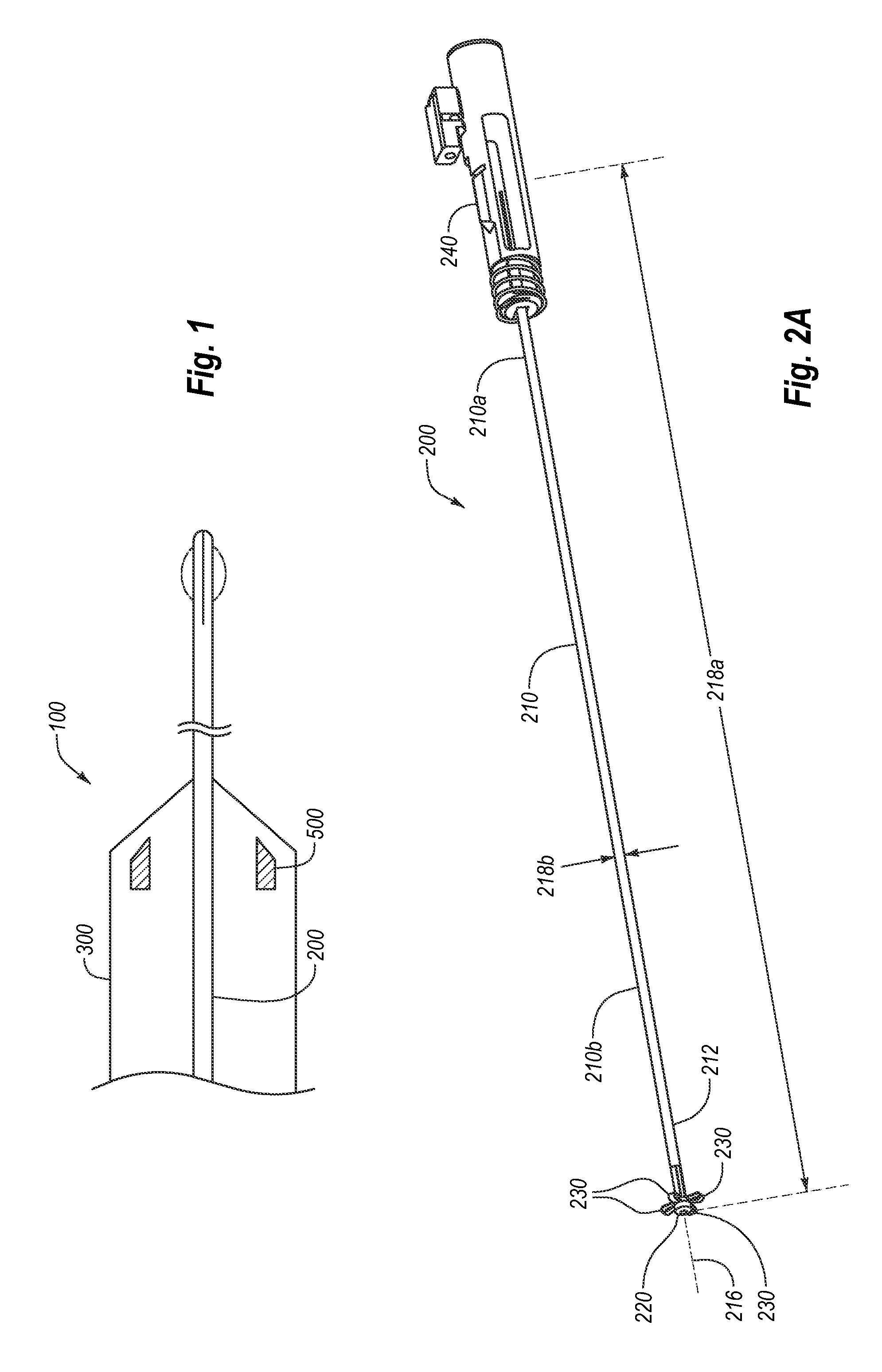
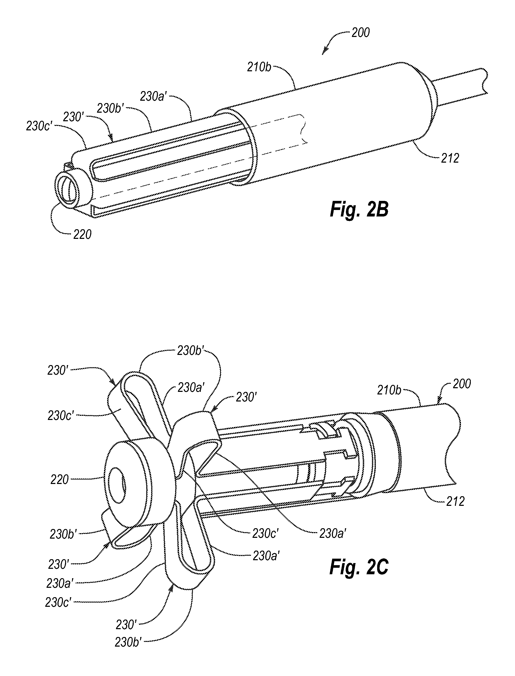
[0266]The embodiments described herein extend to methods, systems, and apparatus for managing access through tissue. Some of the apparatuses of the present invention are configured to deliver a device for managing access through tissue into an opening formed in and / or adjacent to tissue. Embodiments are additionally directed to an apparatus and method for delivering a closure element through tissue and into an opening formed in, or adjacent to, a wall of a blood vessel or other body lumen of any size.

[0267]The apparatus can be configured to receive and retain the closure element such that the closure element is disposed substantially within the apparatus. Thereby, if the apparatus is introduced via an introducer sheath, for example, the closure element can be disposed within, and delivered by way of, a lumen of the introducer sheath. The apparatus also is configured to engage the blood vessel wall adjacent to the opening and to position the closure element substantially adjacent to ...


PUM


Abstract

An apparatus for delivering a closure element can include a splittable carrier tube and a splitter to split the tube. The carrier tube can have an outer surface retaining a closure element in a tubular configuration and can be split into radially-expandable flaps. A closure element can have a shape-memory body having a relaxed configuration with a planar-annular body defining a lumen with tines directed inwardly from the body. The clip can be held in a retaining configuration having a substantially asymmetrically-elongated tubular shape with a trapezoidal longitudinal cross-sectional profile and a proximal end having the tines being longitudinally directed with a first tine being more distally oriented compared to a substantially opposite second tine being more proximal, and retracting to a deploying configuration having a tubular shape with a rectangular longitudinal cross-sectional profile with the first tine being even with the second tine when being delivered.

Description

CROSS-REFERENCE TO RELATED APPLICATIONS[0001]This application is a continuation-in-part of U.S. patent application Ser. No. 12 / 973,204, filed Dec. 20, 2010, now U.S. Pat. No. 8,202,294, which is a divisional of U.S. patent application Ser. No. 11 / 048,503, filed Feb. 1, 2005, now U.S. Pat. No. 7,857,828, which is a continuation-in-part of U.S. patent application Serial No. 10 / 638,115, filed Aug. 8, 2003, now U.S. Pat. No. 7,867,249, which is a continuation-in-part of U.S. patent application Ser. No. 10 / 356,214, filed Jan. 30, 2003, now U.S. Pat. No. 7,905,900, each of which are incorporated herein by specific reference in its entirety. This application is also a continuation-in-part of U.S. patent application Ser. No. 11 / 852,190, filed on Sep. 7, 2007, which claims benefit of U.S. Provisional Application Ser. No. 60 / 843,325, filed Sep. 8, 2006, each of which are incorporated herein by specific reference in its entirety. This application is also a continuation-in-part of U.S. patent a...

Claims


Application Information

Patent Timeline
Patent Type & Authority Patents(United States)
IPC IPC(8): A61B17/08A61B17/10
CPCA61B17/0057A61B17/064A61B17/068A61B17/10A61B17/0644A61B17/1227A61B2017/0003A61B2017/00106A61B2017/00349A61B2017/00637A61B2017/00668A61B2017/00672A61B2017/0649A61B2017/12018A61B2019/465A61B2090/065A61B17/083
Inventor PALERMO, THOMAS J.BELEF, WILLIAM M.CARLEY, MICHAEL T.GINN, RICHARD S.PANTAGES, ANTHONY J.JABBA, RONALD J.ELLINGWOOD, BRIAN A.VOSS, LAVEILLE KAOMCCRYSTLE, KELLY J.GROSS, T. DANIELKOKISH, ARKADY
Owner INTEGRATED VASCULAR SYST
Learn More