
Ultrasonic torsional mode and longitudinal-torsional mode transducer system

a transducer and ultrasonic technology, applied in the field of transducers, can solve the problems of inconvenient and inconvenient integration of the system illustrated in fig. 1, inability to meet the needs of the application, and inability to integrate the slim ergonomic surgical tool that is both compact and light weight, so as to achieve the effect of improving performance and operating more efficiently

Active Publication Date: 2013-03-12
PIEZOINNOVATIONS
View PDF6 Cites 6 Cited by
  • Summary
  • Abstract
  • Description
  • Claims
  • Application Information

AI Technical Summary

Benefits of technology

This configuration results in improved performance and efficiency for ultrasonic transducers, enabling smaller, lighter, and more powerful handpieces for medical and industrial applications, with reduced energy coupling issues and optimized energy delivery to the operative site.

Problems solved by technology

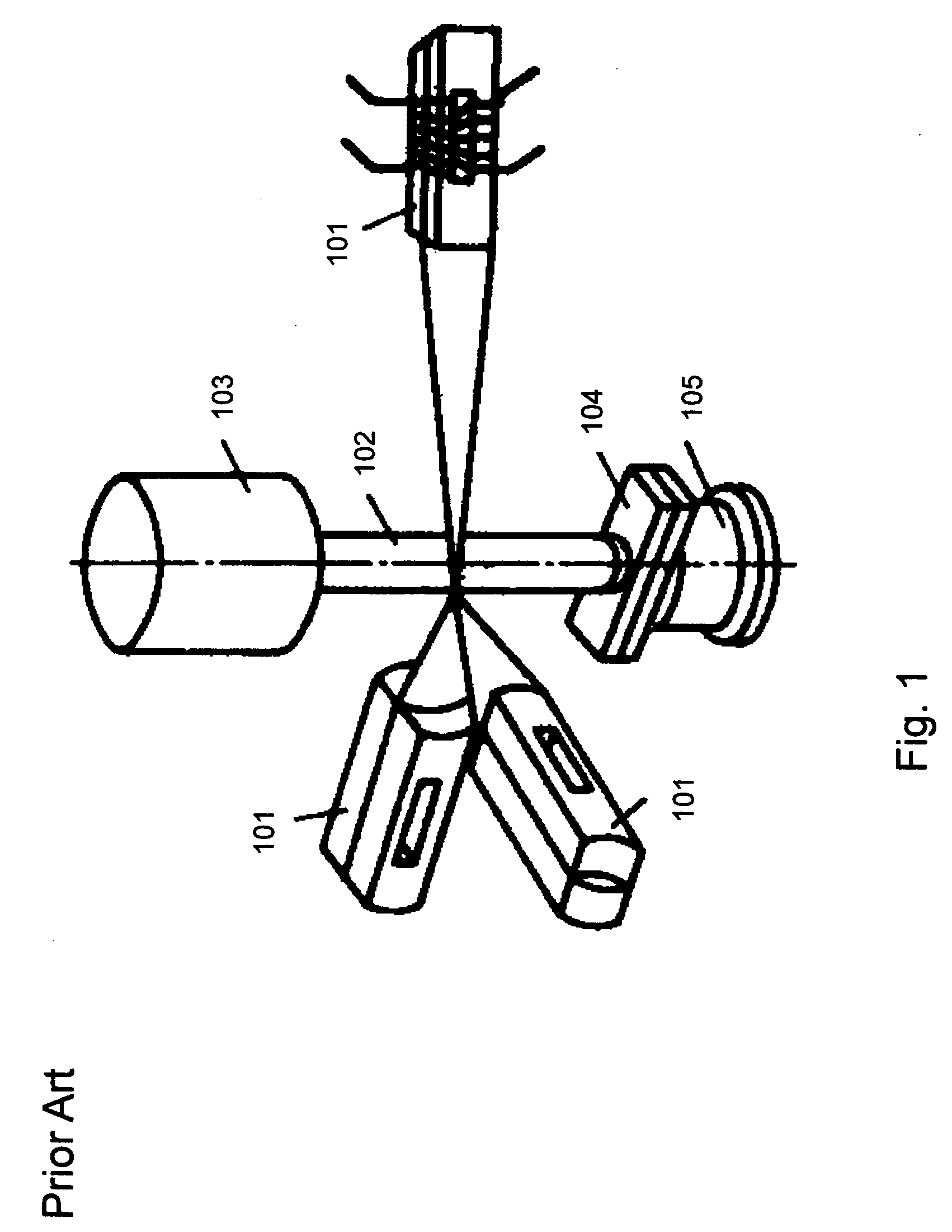
Mitskevich concludes that the system illustrated in FIG. 1 is awkward, inconvenient and extremely unsuitable from the energy point of view.
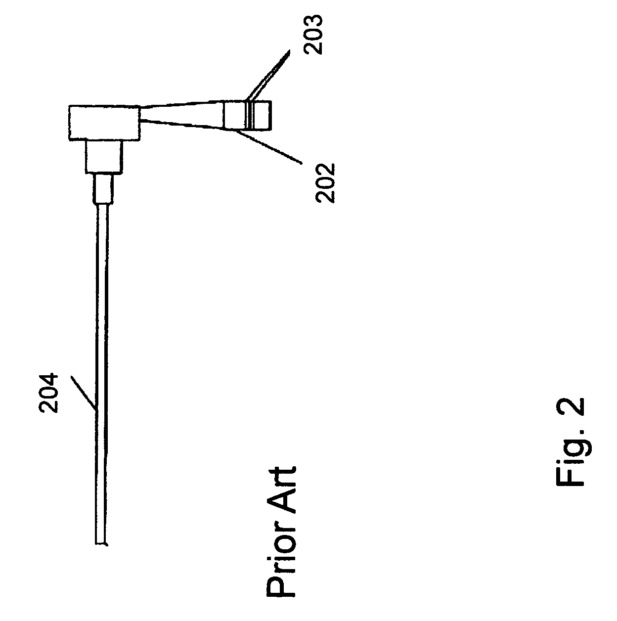
One disadvantage of this design geometry is that it is difficult to incorporate within a slim ergonomic surgical tool that is both compact and light weight.
This length is significantly longer than existing current designs and would be heavier, thus making it impractical to use for these applications.
Although, vibration isolators can be utilized to prevent the communication of such unintended motion, if they are truly isolating they invariably complicate construction of the device and, if simple, consume power in the form of heat generated by contact with a moving surface.
Hence, Boukhny's device is both complicated to operate, needing two separate power sources, and is difficult to construct.
This can present a system control problem and the high operating voltage limits the torsional mode power that can be delivered to the operative site.
Therefore, as to these L-T transducer systems, Rozenberg in “Sources of High-intensity Ultrasound,” Volume 2 concludes that “despite the number of obvious advantages of Longitudinal-Torsional mode (L-T) systems, they have not been put to use on a sufficient scale.
One of the main reasons for this is a lack of at least an approximate method for the calculation of such systems” This problem is compounded because the experimental optimization process is complex and involves the fabrication of a large number of sample L-T waveguides.

Method used


Image

  • Ultrasonic torsional mode and longitudinal-torsional mode transducer system
  • Ultrasonic torsional mode and longitudinal-torsional mode transducer system
  • Ultrasonic torsional mode and longitudinal-torsional mode transducer system

Examples


Embodiment Construction

A. Terms and Definitions

[0041]The following terminology and definitions apply as used in the present application.

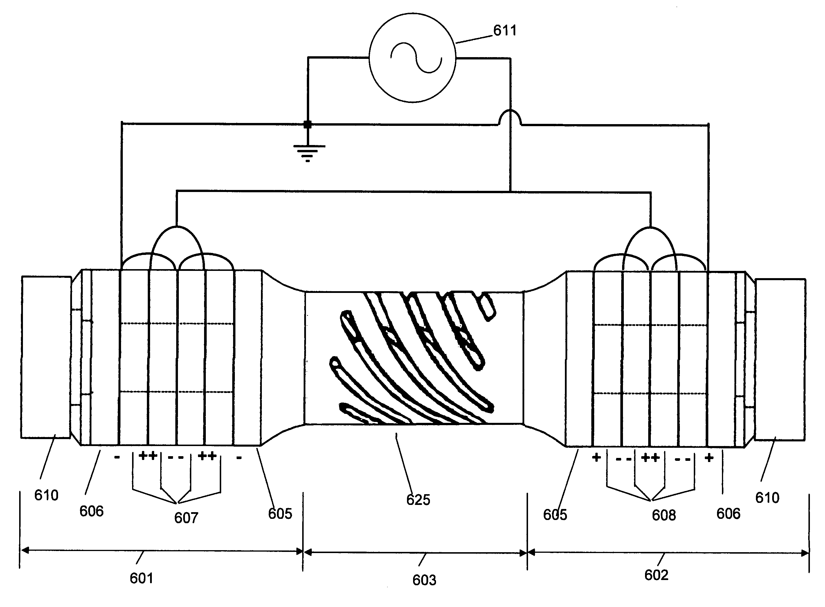
[0042]The phrase “inhomogeneous resonator” refers to a component, such as for example, but not limitation, a rod, bar, spring, with a non-uniform cross sectional region that generates torsional and longitudinal motion. In some embodiments, an inhomogeneous resonator is a spiral spring or a twisted bar. In other embodiments, a inhomogeneous resonator is a rod with one or more slots.

[0043]The phrase “piezoelectric stack” means a two or more piezoelectric elements, such as for example, but not limited to, piezoelectric rings, electrically connected in parallel, which are stacked or held in compression by a bolt or other means. A piezoelectric stack can optionally have an endmass coupled to one or both of the outer piezoelectric elements.

B. Transducer Subassemblies and Systems of the Invention

[0044]The present invention is directed to ultrasonic transducer subassemblies and s...


PUM


Abstract

The present invention relates to the design of piezoelectric transducer subassemblies and systems primarily intended for medical and dental applications. The invention also provides transducer subassemblies and systems with improved performance and a capability to operate more efficiently in torsional or a combined longitudinal-torsional mode of vibration. The invention enables the size and weight of torsional mode transducers to be reduced. Additionally, the electrical characteristics of these transducer systems are improved, thus enabling the transducer end effector to deliver more power to the operative site.

Description

CROSS REFERENCE TO RELATED APPLICATIONS[0001]This application claims priority under 35 U.S.C. §119 from Provisional Application Ser. No. 61 / 066,800, filed Feb. 22, 2008, the disclosure of which is incorporated herein by reference.FIELD OF THE INVENTION[0002]The invention generally relates to the field of transducers. More specifically, this invention relates to transducers configured to produce torsional motion or longitudinal-torsional motion at ultrasonic frequencies.BACKGROUND OF THE INVENTION[0003]Torsional mode transducer systems have been described extensively in a book entitled “Sources of High-intensity Ultrasound,” Volume 2, and more specifically in Part IV, which is entitled “Torsional Mode Vibration Systems,” written by A. M. Mitskevich and edited by Rozenberg in 1969. FIG. 1 illustrates one type of a torsional mode system disclosed therein. The system illustrated in FIG. 1 is normally used for welding, for example, in specialist applications such as the helium tight seal...

Claims


Application Information

Patent Timeline
Patent Type & Authority Patents(United States)
IPC IPC(8): H01L41/083H10N30/50H10N30/88
CPCB06B1/0611A61B17/320068A61B2017/320096A61C1/07A61B2017/320098A61B2017/32007A61B2017/320089
Inventor BROMFIELD, GEORGE
Owner PIEZOINNOVATIONS
Learn More