Fixing device including endless fixing belt, heating member and tension roller

a fixing device and heating member technology, applied in the direction of instruments, electrographic process equipment, optics, etc., can solve the problems of insufficient heat supply, speeding up processing speed, and temperature of the fuser roller not keeping up with processing speed, so as to reduce the driving torque of the fixing belt, wide heating nip width, and reduce the effect of any damag

Active Publication Date: 2013-03-05
SHARP KK
View PDF19 Cites 6 Cited by
  • Summary
  • Abstract
  • Description
  • Claims
  • Application Information

AI Technical Summary

Benefits of technology

[0015]According to the configuration of the present invention, the fixing belt is provided across a fixing member, a heating member, and a tension roller, in a tensioned state. Hence, it is possible to reduce the driving torque of the fixing belt as well as reducing any damage given to the fixing belt. Moreover, the tension roller is determined in position on the fixing belt so that a length of the fixing belt upstream of the fixing nip area in a fixing belt rotating direction, from the tension roller to the fixing member, is longer than that downstream of the fixing nip area in the fixing belt rotating direction, from the fixing member to the tension roller. This provides a space to dispose the heating member on the upstream side of the fixing nip area. As a result, it is possible to have a wide heating nip width. Moreover, by having the downstream side in the fixing belt rotating direction be shorter than the upstream side in the fixing belt rotating direction, a distance in which the fixing belt is cooled is made short. As a result, it is possible to prevent the dispersion of heat, thereby allowing more efficient heating of the fixing belt.
[0016]As described above, the fixing device having the foregoing configuration attains excellent heat efficiency and low electricity consumption while preventing occurrence of poor fixing. Moreover, this configuration achieves the reduction in the driving torque of the fixing belt and reduction in damage given to the fixing belt.
[0017]Moreover, the fixing belt is put across the heating member in a tensioned state. That is, the heating member is in contact with the fixing belt from an inner side of the fixing belt. As a result, this prevents the generation of scratches caused by rubbing, on an outer circumferential surface of the fixing belt that directly is in contact with the unfixed image on the recording material.

Problems solved by technology

However, since the thermal conductivity of the elastic layer is extremely low, if heating means is provided as in the conventional fuser roller, inside the fuser roller which has the thickened elastic layer, this would result in insufficient heat supply in the case where the processing speed is sped up.
As a result, a problem arises that the temperature of the fuser roller cannot keep up with the processing speed.
On the other hand, if the diameter of the fuser roller is broadened, problems arise such as that more time is necessary to warm up the fuser roller and that the electricity consumption increases in amount.

Method used


Image

  • Fixing device including endless fixing belt, heating member and tension roller
  • Fixing device including endless fixing belt, heating member and tension roller
  • Fixing device including endless fixing belt, heating member and tension roller

Examples


Embodiment Construction

[0024]One embodiment of the present invention is described below with reference to drawings. The following description explains in details of one embodiment of a fixing device according to the present invention and an image forming apparatus including that fixing device.

[0025](Image Forming Apparatus)

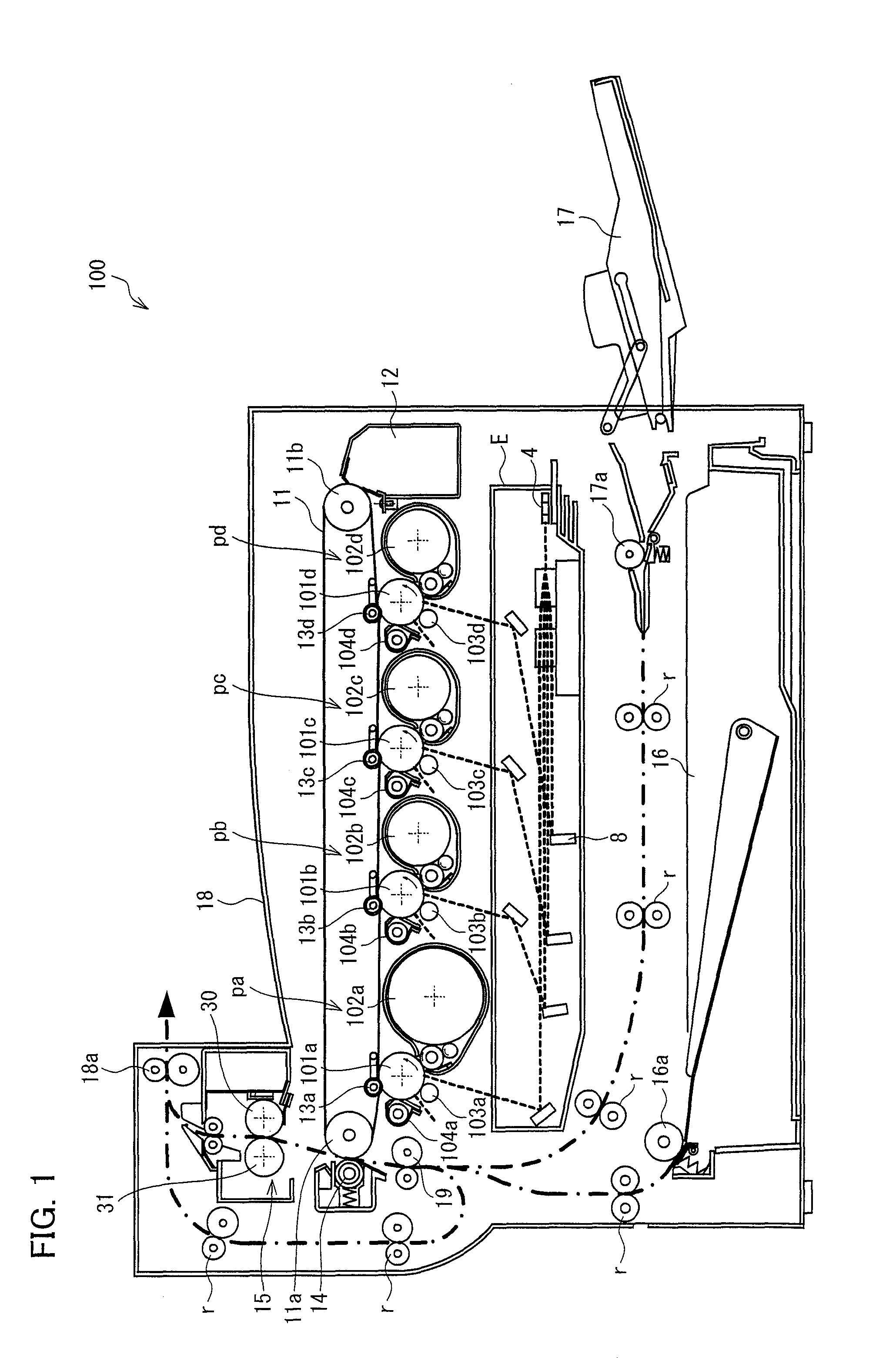
[0026]First described is a configuration of an image forming apparatus of the present embodiment. FIG. 1 is a cross-sectional view schematically illustrating a configuration of an image forming apparatus 100 of the present embodiment. The image forming apparatus 100 is what is called a tandem, color multi-functional peripheral of an intermediate transfer method, which is capable of forming a full color image. Although the present embodiment describes the image forming apparatus according to the present invention as applicable to color multi-functional peripherals (or copying machines) and color printers, the image forming apparatus according to the present invention is also applicable t...


PUM


Abstract

Disclosed is a fixing device including: a fixing belt provided across a fuser roller and a heating member in a tensioned state, which fixing belt is rotated; and a tension roller applying a load on the fixing belt from an inner circumferential side of the fixing belt, which tension roller is determined in position on the fixing belt so that a length of the fixing belt upstream of the fixing nip area in a fixing belt rotating direction, from the tension roller to the fixing member, is longer than that downstream of the fixing nip area in the fixing belt rotating direction, from the fixing member to the tension roller.

Description

[0001]This Nonprovisional application claims priority under 35 U.S.C. §119(a) on Patent Application No. 2010-075138 filed in Japan on Mar. 29, 2010, the entire contents of which are hereby incorporated by reference.TECHNICAL FIELD[0002]The present invention relates to a fixing device used in an image forming apparatus of an electrophotographic printing method, and relates to an image forming apparatus including such a fixing device.BACKGROUND ART[0003]As fixing devices used in image forming apparatuses of an electrophotographic printing method for instance copying machines and printers, fixing devices of a heat roller fusing method have been frequently used. The fixing device of the heat roller fusing method includes: a pair of rollers (fuser roller and pressure roller) that are pressured against each other; and heating means made up of a halogen heater or the like, provided inside either both or one of the pair of rollers. After the heating means heats the pair of rollers to a set ...

Claims


Application Information

Patent Timeline
Patent Type & Authority Patents(United States)
IPC IPC(8): G03G15/20
CPCG03G15/2053G03G15/2039G03G2215/2029
Inventor TANAKA, ATSUSHIYAMANA, SHINJI
Owner SHARP KK
Why Eureka
Try Eureka