Image forming apparatus

a technology of forming apparatus and forming chamber, which is applied in the direction of digital output to print units, instruments, visual presentations, etc., can solve the problems of user misoperation, user inability and difficulty for users to set the desired operational condition

Active Publication Date: 2013-03-05
KYOCERA DOCUMENT SOLUTIONS INC
View PDF17 Cites 0 Cited by
  • Summary
  • Abstract
  • Description
  • Claims
  • Application Information

AI Technical Summary

Benefits of technology

[0008]Thus, an object of the present invention is to provide an image forming apparatus wherein a desired operational condition for the user's intended use can be set without omission and fail.
[0009]Another object of the present invention is to provide an image forming apparatus wherein inoperable operational conditions will not be set by mistake and the desired operational condition can be set easily.
[0010]Yet another object of the present invention is to provide an image forming apparatus having a plurality of operational modes with each of them having a plurality of operational conditions, wherein the set content of the operational condition that has been already set can be changed without returning to the original set mode screen from which the user has set.

Problems solved by technology

According to this publication, even if the user selects the display screen having few display items, it is possible that the user cannot set the desired operational condition by selecting the displayed item and an unnecessary item is displayed.
In this case, although there are only a small number of display items, it is possible that the user makes a mistake in setting of the operational condition and it may be difficult for the user to set the desired operational condition.
However, it is not always easy for the user to set the operational condition for the user's intended use even if the user has selected an optimum display screen from a plurality of display screens.
This is because it is not necessarily possible to set the operational condition suitable for the user's intention from the displayed screen.
Moreover, even if the image forming apparatus has the operational condition suitable for the user's intended use, the user possibly forgets to set the operational condition.
However, when the content of the operational condition that has been set is to be changed, the user must return to the original set mode screen from which the user can reset the set content and this is troublesome.

Method used


Image

  • Image forming apparatus
  • Image forming apparatus
  • Image forming apparatus

Examples


first embodiment

1. First Embodiment

[0057]Firstly, an operation example wherein the control unit 11 selects an operational condition that is operable according to a first embodiment of the present invention will be described below. FIG. 3 is a flow chart showing the operation of the control unit 11 when the multi functional printer 10 is used as a copy machine. With reference to FIGS. 2 and 3, the operation of the control unit 11 will be described below wherein the document is copied using the support function.

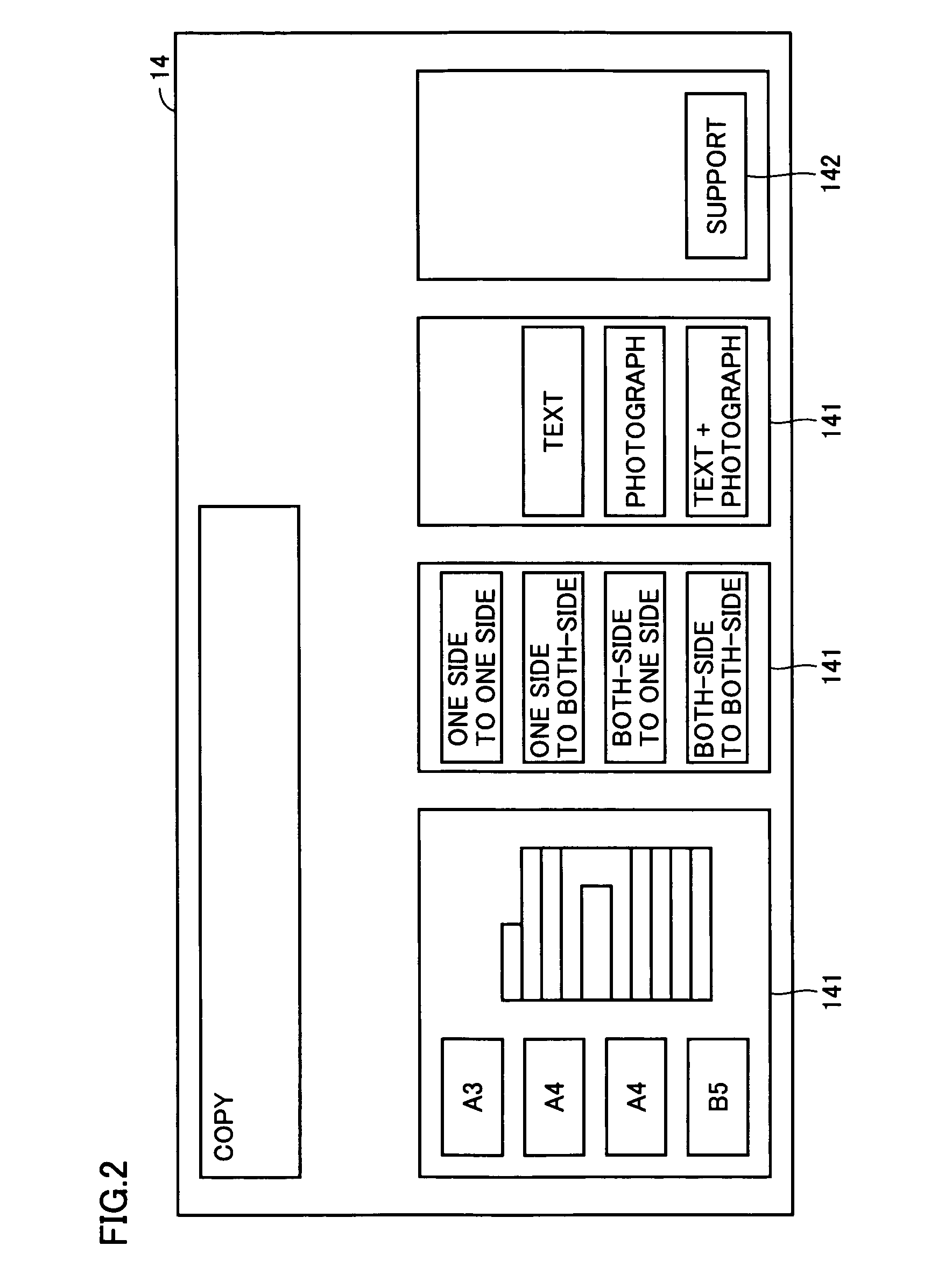
[0058]At first, the user selects whether or not to use the support function. The support function means a function to display operable operational conditions on the operating unit 14 in turn for each operational condition on the basis of the reading result of the document and the inputted information about an intended use of the user. In order to use this function, the support function key 142 displayed on the operating unit 14 is pressed down.

[0059]In step (in the drawing, abbreviated as SP) ...

second embodiment

2. Second Embodiment

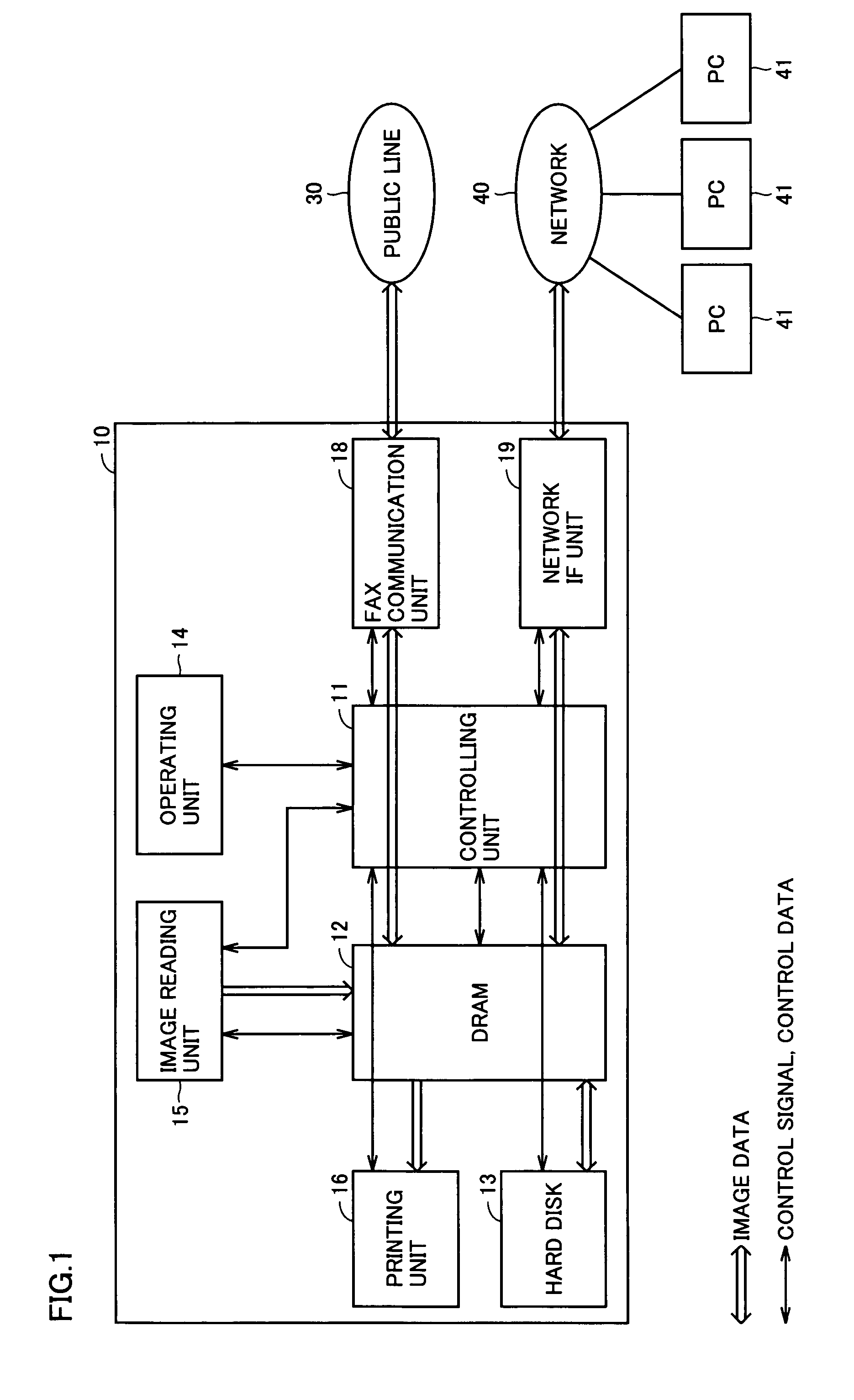
[0073]Next, a second embodiment of the present invention will be described below. Also in the following embodiments including the second embodiment, the structure of the image forming apparatus shown in FIG. 1 and FIG. 2 and the display on the screen of the operating unit 14 are the same as in the first embodiment.

[0074]FIG. 9 is a flow chart showing the operation of the control unit 11 when the multi functional printer 10 according to the second embodiment of the present invention is used as a copy machine and this corresponds to FIG. 3 of the first embodiment. With reference to FIG. 2 and FIG. 9, the operation of the control unit 11 in copying with the support function will be described below.

[0075]In FIG. 9, steps shown in steps SP11 to SP14 are the same as those shown in steps SP1 to SP4 in FIG. 3 according to the first embodiment, so that the explanation thereof is not reiterated.

[0076]After reading the document as either the one side copy or the both-side d...

third embodiment

3. Third Embodiment

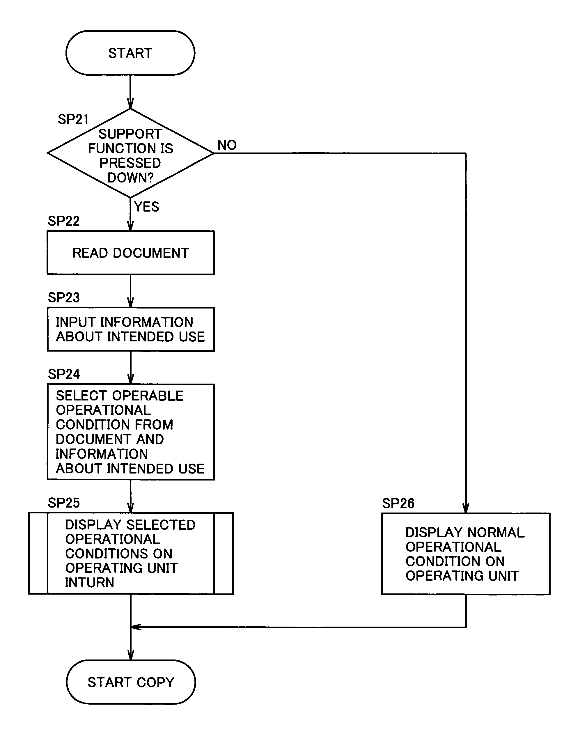
[0089]Next, a third embodiment according to the present invention will be described below. FIG. 12 is a flow chart showing the operation of the control unit according to the present embodiment. With reference to FIG. 2 and FIG. 12, the operation of the control unit 11 in copying the document using the support function will be described below.

[0090]In the step SP21, when the support function key 142 is pressed down (YES in the SP21), the image reading unit 15 reads the document set by the user by the automatic document feeder or the document table (SP22).

[0091]After reading the document, the user is made to input the information about the intended use in forming an image in the step SP23. In this case, the display example of the operating unit 14 for making the user input the information about the intended use is the same as FIG. 5 shown in the first embodiment and the number of the read document, an inquiry of “what is an intended use?” to prompt the user to input...


PUM


Abstract

An image forming apparatus determines if a support function key is pressed down or not. When it is determined that the support function key is pressed down, the image forming apparatus determines if the read document is a one side document or a both-side document. Then the document is read and operable operational conditions are selected based on the read document and the information about an intended use that is inputted by a user. The selected operational conditions are displayed on an operating unit for each operational condition. As a result, it is possible to provide an image forming apparatus wherein the user can set a desired operational condition easily suitable for the user's intended use without omission and fail.

Description

BACKGROUND OF THE INVENTION[0001]1. Field of the Invention[0002]The present invention relates to an image forming apparatus, and particularly, to an image forming apparatus which can be easily operated.[0003]2. Description of the Related Art[0004]The image forming apparatus, wherein operating unit has a plurality of display screens displaying different display items and user can select a desired display screen in accordance with the user's preference, is disclosed in, for example, Japanese Unexamined Patent Publication No. 11-194669. According to Japanese Unexamined Patent Publication No. 11-194669, a visibility and user-friendliness of the operating unit are improved by making the user select either the display screen having few display items or the display screen having many display items and operate the image forming apparatus through the selected display screen.[0005]According to this publication, even if the user selects the display screen having few display items, it is possib...

Claims


Application Information

Patent Timeline
Patent Type & Authority Patents(United States)
IPC IPC(8): G06F3/12G06K15/00
CPCH04N1/00408H04N1/00411H04N1/00416H04N1/00437H04N1/00482H04N2201/0094
Inventor ITOU, SHIGEHARU
Owner KYOCERA DOCUMENT SOLUTIONS INC
Why Eureka
Try Eureka