
Apparatus for and methods of stabilizing a leaking dam or levee

a technology applied in the field of apparatus for and methods of stabilizing a leaking dam or levee, can solve the problems of destroying the protective features affecting the stability of earth dams and levees, so as to facilitate the stopping of undesirable water leakage, maintain and stabilize the integrity of the dam

Inactive Publication Date: 2013-03-05
CHRISTENSEN ARTHUR E
View PDF7 Cites 0 Cited by
  • Summary
  • Abstract
  • Description
  • Claims
  • Application Information

AI Technical Summary

Benefits of technology

The invention is about creating a device and methods to stop water leaks in dams and stabilize them for continued use. It is designed to be portable, affordable, and easy to use, even in remote locations. The device includes a flexible sheet made of impervious material that can be placed over a breach in the dam or levee to stop leaks and maintain the integrity of the structure. A spool and cord are used to secure the device and move it into position. The device can be easily moved and adjusted for different breach sizes, and can be reused and stored when not in use. The technical effects of this invention are to provide a reliable and affordable solution for stopping water leaks in dams and maintaining their integrity, even in remote locations where high-cost repairs may not be available. Additionally, it provides a cost-effective solution for stabilizing dam structures in the event of leaks or breaches.

Problems solved by technology

However, weather-related incidents, such as, for example, wind storms and rain, can result in excess amounts of water along at least sections of the quiescent bodies and the waterways, where the water level thereof extends beyond the shoreline and the banks, respectively, resulting in devastating flooding of areas adjacent the bodies and waterways.
Such flooding is widely known for causing loss of life and property damage.
Dams and levees formed by compacted soil, and the like, are typically referred to as earth dams and levees, and are susceptible to breaches in the soil, which weaken and erode the protective features of the earth dams and levees.
While the major constituent of earth dams is compacted soil, such dams may also include a limited amount of rocks, pebbles, and the like.
While man-made dams composed of concrete and the like are generally considered as breach-free structures, breaches do occur in such dams, thereby lessening the integrity of the dam.
However, as noted above, man-made and natural dams, composed primarily of compacted soil, are particularly susceptible, under the hydrostatic pressure of the contained body of water, to erosion.
Such erosion causes leaks through the dams, which could cause the dams to collapse in the vicinity of the erosion.
As noted in the article, “Thousands of the nation's dams, for instance, are rated structurally deficient, and no fewer than 1800 of those are rated “high hazard” dams, meaning their catastrophic failure would result in significant loss of life.”
In today's economic climate, it is highly unlikely that such a large infrastructure investment will be made.
Consequently, there is a need for a relatively low cost apparatus for and methods of facilitating the stabilization and maintenance of the nation's dams, particularly during a period when it appears that high-cost repairs and reconstruction to such “high hazard” dams may not be forthcoming.
Such an extensive cover for an entire dam would be very costly in order to protect the entire dam in the manner described in the '786 patent.
Also, the type of material of the cover, as described in the '786 patent, is an organic material which may become brittle and crack under prolonged exposure to the environment, including debilitating stresses to which a cover for an earth dam is typically subjected.
In particular, organic materials soften and deform irreversibly at temperatures greater than 100° C., and become brittle at temperatures less than −25° C.

Method used


Image

  • Apparatus for and methods of stabilizing a leaking dam or levee
  • Apparatus for and methods of stabilizing a leaking dam or levee
  • Apparatus for and methods of stabilizing a leaking dam or levee

Examples


Embodiment Construction

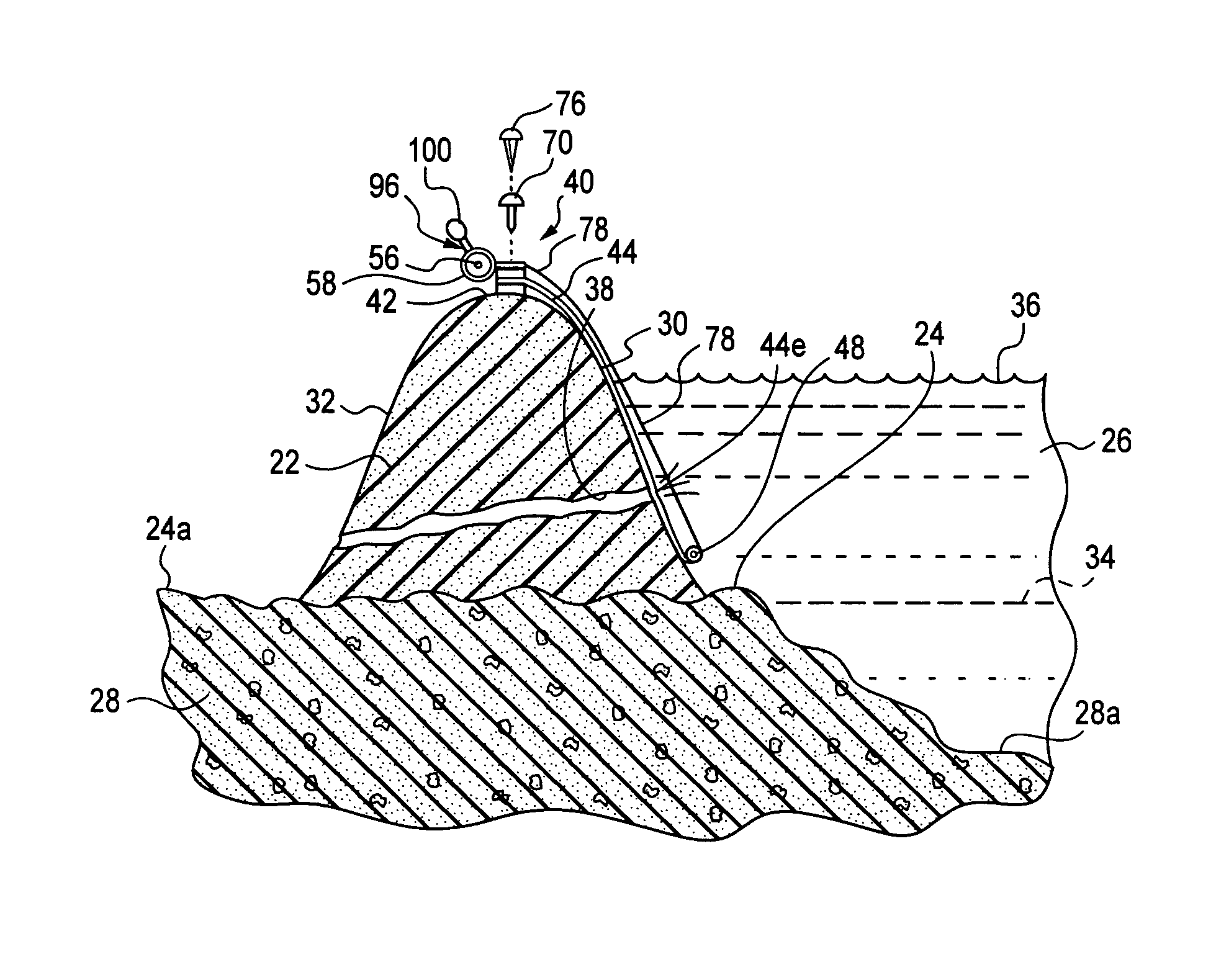
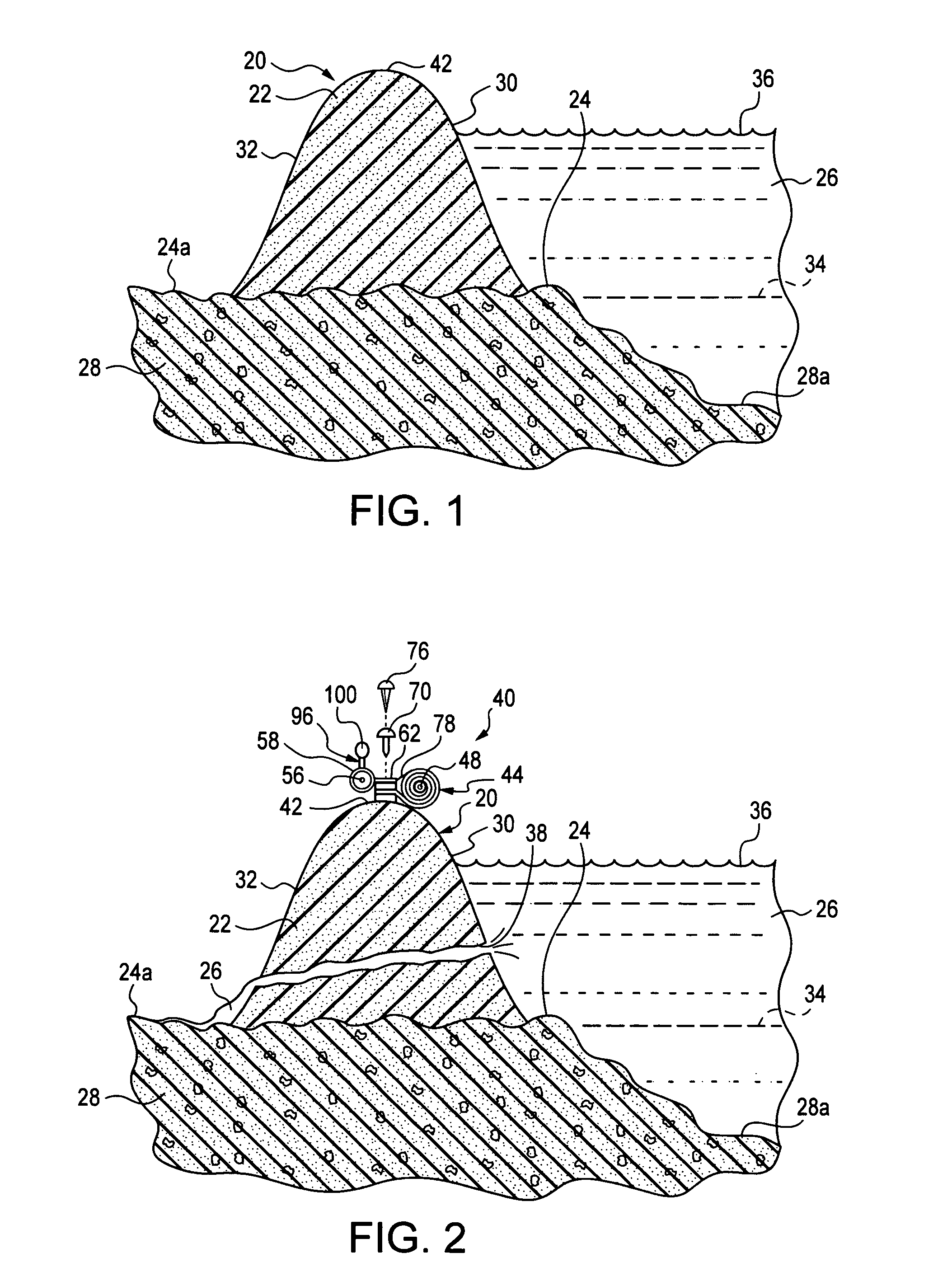
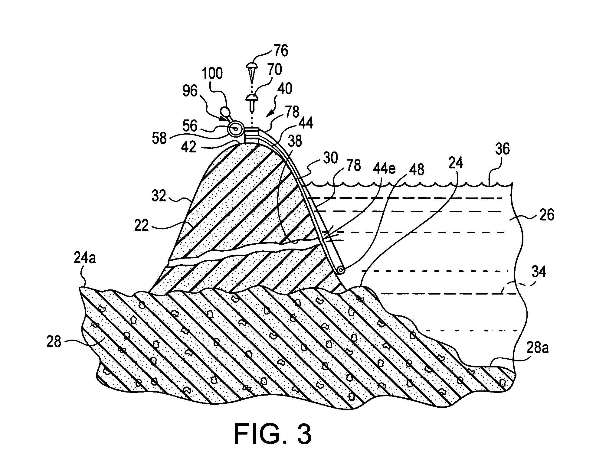
[0031]Referring to FIG. 1, an earth dam 20 is formed with a mound-like cross section, and is composed of compacted soil 22, which could include limited amounts of rock and pebble. The earth dam 20 is located along the shoreline or bank 24 of a body of water, hereinafter referred to as the water 26. The bank 24 is formed by an upper level of a land mass 28, with a depression in the land mass forming a bed 28a for the water 26. The water 26 may be quiescent, such as, for example, in a lake, or moving, such as, for example, in a canal. The earth dam 20 is formed with a water-covered side 30, which is in engagement with the water 26, and an uncovered side 32, which is on a side of the dam opposite from the water-covered side. The earth dam 20 must be of sufficient integrity to withstand the hydrostatic pressure exerted thereon by the water 26.

[0032]Normally, the upper level of the water 26 will be below the bank 24, as illustrated by the dashed line 34 in FIG. 1. Under this circumstance...


PUM


Abstract

An apparatus 40 is used for stabilizing a leak in a dam 20, which was built adjacent a body of water 26 to prevent flooding of the water onto adjacent land areas 24a. Leaks in the dam 20 may occur because of a breach 38 developing undesirably in, and possibly through, the dam. The apparatus 40 includes an elastomeric sheet 44, which is wound onto a spool 48, when the apparatus is in a storage-and-handling mode. When the breach 38 is discovered, the apparatus 40 is placed adjacent the dam 20 and the sheet 44 is unfurled into a breach-sealing mode of the apparatus, where the breach 38 is covered and sealed by the unfurled sheet.

Description

BACKGROUND OF THE INVENTION[0001]This invention relates to apparatus for and methods of stabilizing a leaking dam or levee, and particularly relates to apparatus for and methods of stopping leaks through dams such as, for example, earth dams, typically located along the banks of quiescent bodies of water, and levees along waterways, which contain moving water.[0002]A quiescent body of water typically includes lakes, reservoirs, and the like, which are contained within a completely enclosing shoreline, where, normally the water does not escape or flow from within the quiescent body. Waterways of moving water include canals, rivers, and the like, where the water is typically continuously flowing along the banks thereof, which confines the flowing water between the banks, where the flowing water eventually empties into a larger body of water such as, for example, a sea or an ocean.[0003]As long as there are no incidents which cause the level of the water to rise in the quiescent bodies...

Claims


Application Information

Patent Timeline
Patent Type & Authority Patents(United States)
IPC IPC(8): E02B7/00
CPCE02B3/10E02B3/122Y02A10/11
Inventor CHRISTENSEN, ARTHUR E.
Owner CHRISTENSEN ARTHUR E
Learn More