
Installation device for slide assembly

a technology of installation device and slide assembly, which is applied in the mounting of support structures, domestic applications, servers, etc., can solve the problems of inconvenient user experience, difficulty for a user to separate the server from the rails, and improper lifting or deformation of positioning members

Active Publication Date: 2013-02-05
KING SLIDE WORKS CO LTD +1
View PDF14 Cites 16 Cited by
  • Summary
  • Abstract
  • Description
  • Claims
  • Application Information

AI Technical Summary

Benefits of technology

The present invention relates to a device for installing a slide assembly. It includes a first rail and a second rail that can slide back and forth along the first rail. A positioning member is used to position the second rail, which has a hole and a guide seat. A release member is used to secure the second rail to the positioning member. The release member has a reception portion, a connection board, and an operation portion. When the operation portion is moved, the release member moves along the second rail and positioned itself. The positioning hole of the arm board has a top and bottom inside, which are bent to be guide wings that extend towards a direction away from the second rail. The release member has two blocks that engage with elongate holes in the second rail. The protrusion of the release member has an inclined surface that corresponds to the end piece of the end board of the positioning member. The device simplifies the installation process of a slide assembly and makes it easier to adjust the position of the slide assembly.

Problems solved by technology

This is inconvenient for the users.
If the exterior equipment is a server for a computer, the server is heavy so that it is difficult for a user to separate the server from the rails.
The positioning member may be improperly lifted or deformed by squeezing.
Besides, the allocation of the positioning member, the release member and the inner rails does not meet the requirement of the latest servers, so that an improved installation device is needed.

Method used


Image

  • Installation device for slide assembly
  • Installation device for slide assembly
  • Installation device for slide assembly

Examples


Embodiment Construction

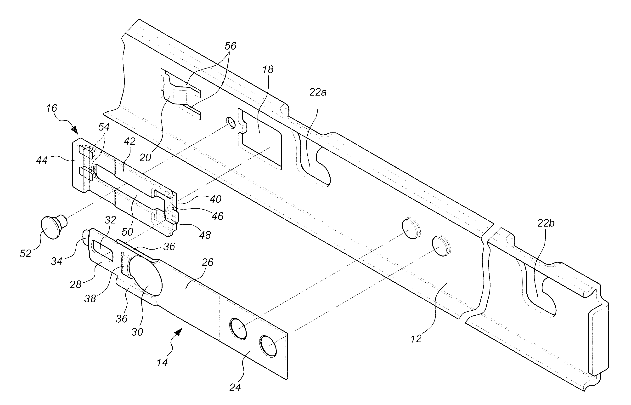
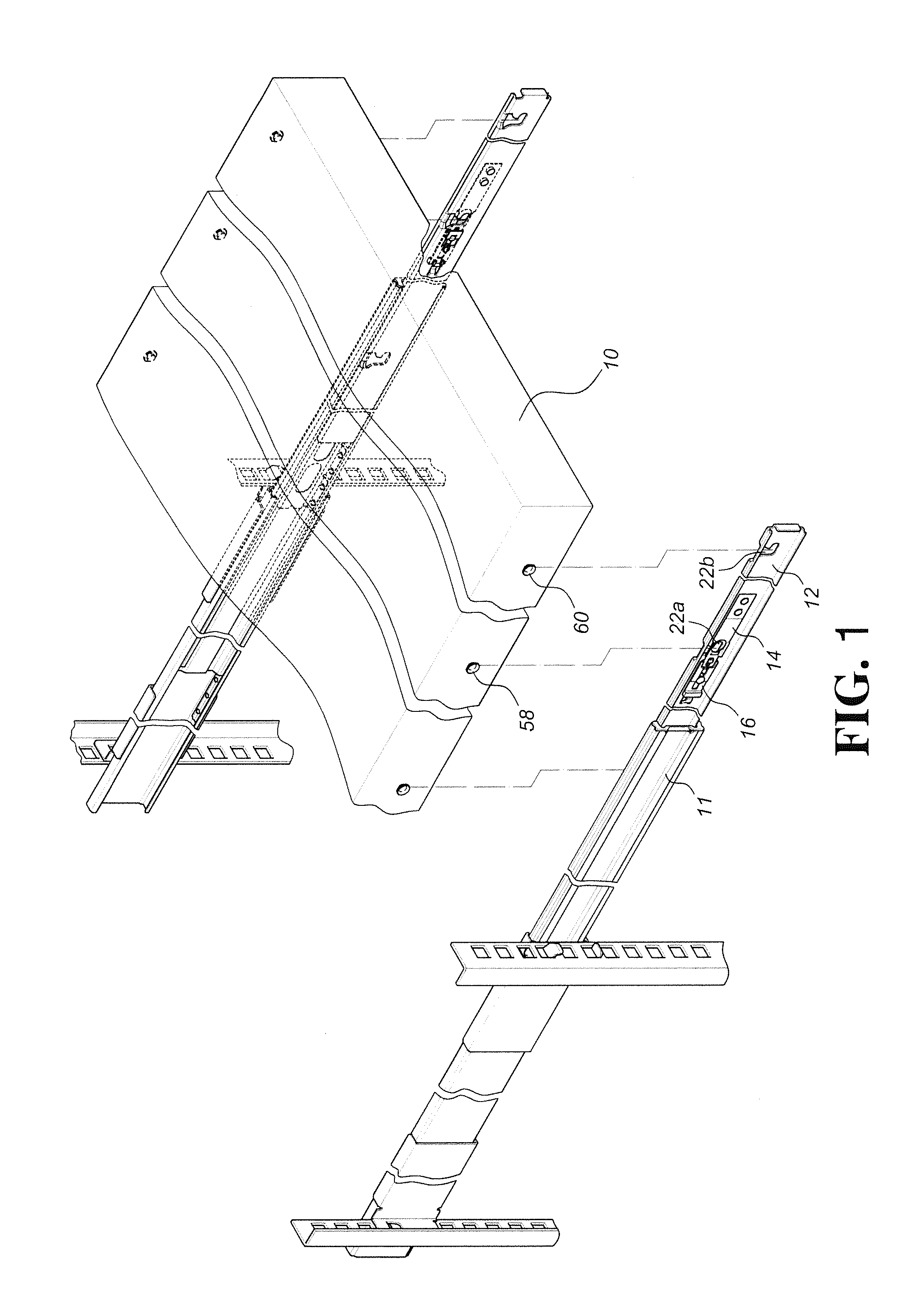
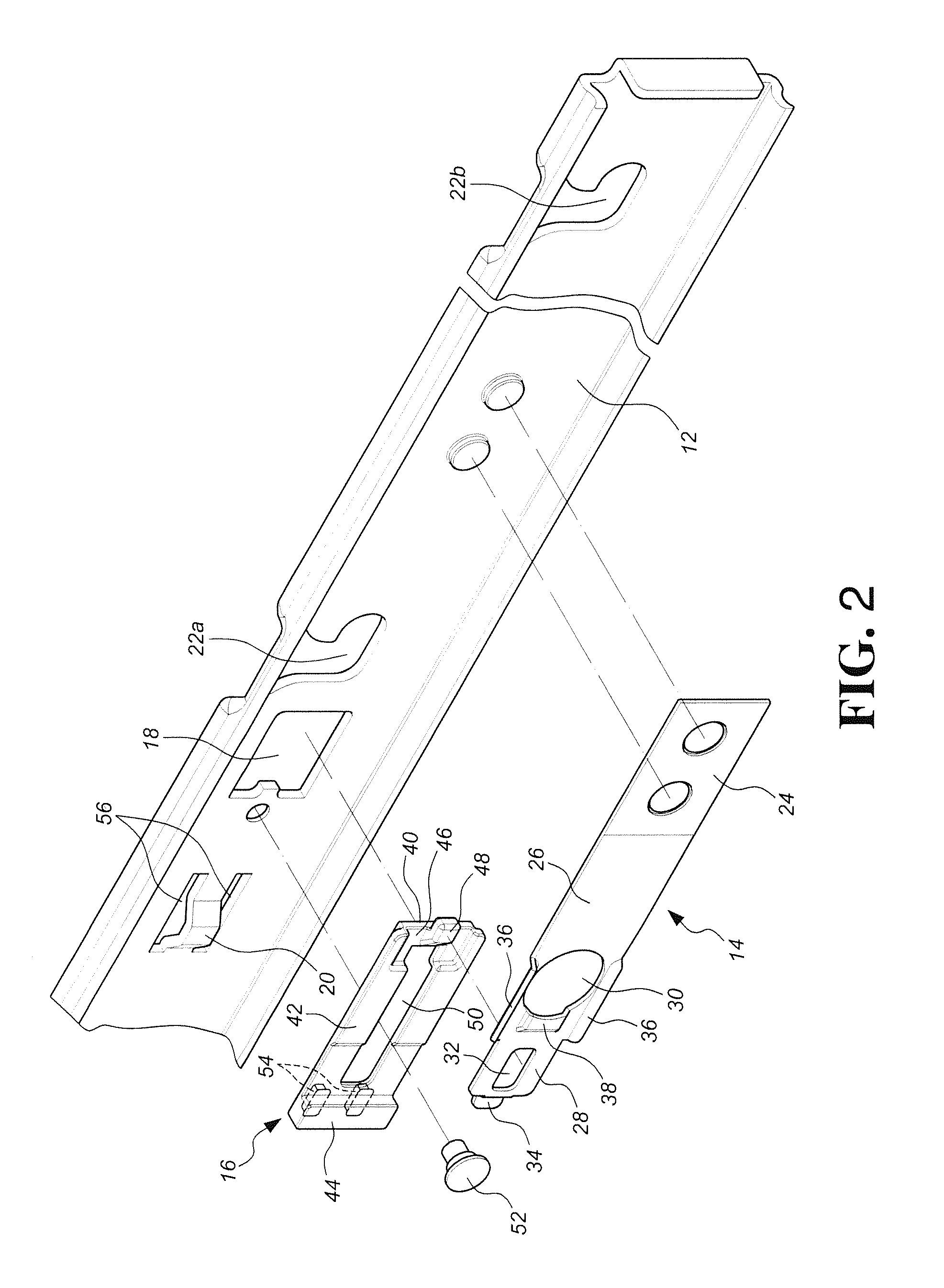
[0021]FIG. 1 shows an exterior equipment 10, such as a server, installed to the slide assembly on a rack system and FIGS. 2 and 3 respectively show the exploded view and the perspective view of the slide assembly of the present invention. The preferable embodiment of the present invention comprises a first rail 11, a second rail 12 slidably connected to the first rail 11, a positioning member 14 and a release member 16.

[0022]The second rail 12 has a hole 18, a guide seat 20, and at least one first slot 22a and a second slot 22b, wherein the hole 18 is located adjacent to the first slot 22a.

[0023]The positioning member 14 has a base 24, an arm board 26 and an end board 28. The base 24 is fixed to the second rail 12. The arm board 26 is connected between the base 24 and the end board 28. The arm board 26 has a positioning hole 30 located corresponding to the first slot 22a of the second rail 12. Preferably, the arm board 26 contacts the second rail 12 and the positioning hole 30 is l...


PUM


Abstract

An installation device for a slide assembly includes a first rail and a second rail which has a guide seat and two slots for being connected with an exterior equipment. A positioning member is fixed to the second rail and an arm board has a positioning hole located corresponding to one of the slots of the second rail so that one of installation members of the exterior equipment is engaged with the positioning hole. An end board has a through hole and an end piece extending toward the second rail. The release member is movably installed to the second rail. When the release member is moved by an exterior force and positioned by the guide seat, the protrusion of the release member pushes the end piece to keep the positioning hole away from the second rail and the exterior equipment is removed from the positioning hole.

Description

FIELD OF THE INVENTION[0001]The present invention relates to an installation device for a slide assembly, and more particularly, to an installation device allowing an exterior equipment to be quickly installed to the slide assembly.BACKGROUND OF THE INVENTION[0002]The conventional exterior equipment such as a drawer is installed to the slide assembly by fixing two inner rails to the two sides of the drawer by screws, or by setting pins to the metal drawer so as to be connected with holes or plates of the rails. The latest techniques are more convenient to fix these parts and some of the techniques are used to the racks for servers of computers, such as disclosed in U.S. Pat. Nos. 4,331,369, 5,632,542, 6,123,314, 6,209,979 B1, 6,588,866 B2, 6,601,933 B1, 6,938,967 B2, 6,948,691 B2, 7,481,504 B2, 7,604,307 B2 and U.S. Patent Laid-Open Publication No. 2004 / 0108797 A1.[0003]In the above mentioned prior arts, the resilient plate or swing plate that contacts the protrusions on two sides o...

Claims


Application Information

Patent Timeline
IPC IPC(8): A47B95/00
CPCA47B88/044H05K7/1489A47B88/43
Inventor CHEN, KEN-CHINGHUANG, SHIH-LUNGFANG, CHIANG-HSUEHWANG, CHUN-CHIANG
Owner KING SLIDE WORKS CO LTD
Learn More