
Short circuit and open circuit protection for a boost converter

a short circuit and open circuit protection technology, applied in the direction of dc-dc conversion, power conversion systems, and arrangements responsive to excess voltage, can solve the problems of damage to power switches, damage to certain components, and inrush of large amounts, so as to prevent the damage of open circuit and prevent the damage of the boost converter

Active Publication Date: 2013-01-29
RICHTEK TECH
View PDF2 Cites 12 Cited by
  • Summary
  • Abstract
  • Description
  • Claims
  • Application Information

AI Technical Summary

Benefits of technology

The solution effectively prevents component damage by controlling the load disconnect switch and managing fault conditions, reducing inrush currents and ensuring safe operation of the boost converter during startup and normal operation.

Problems solved by technology

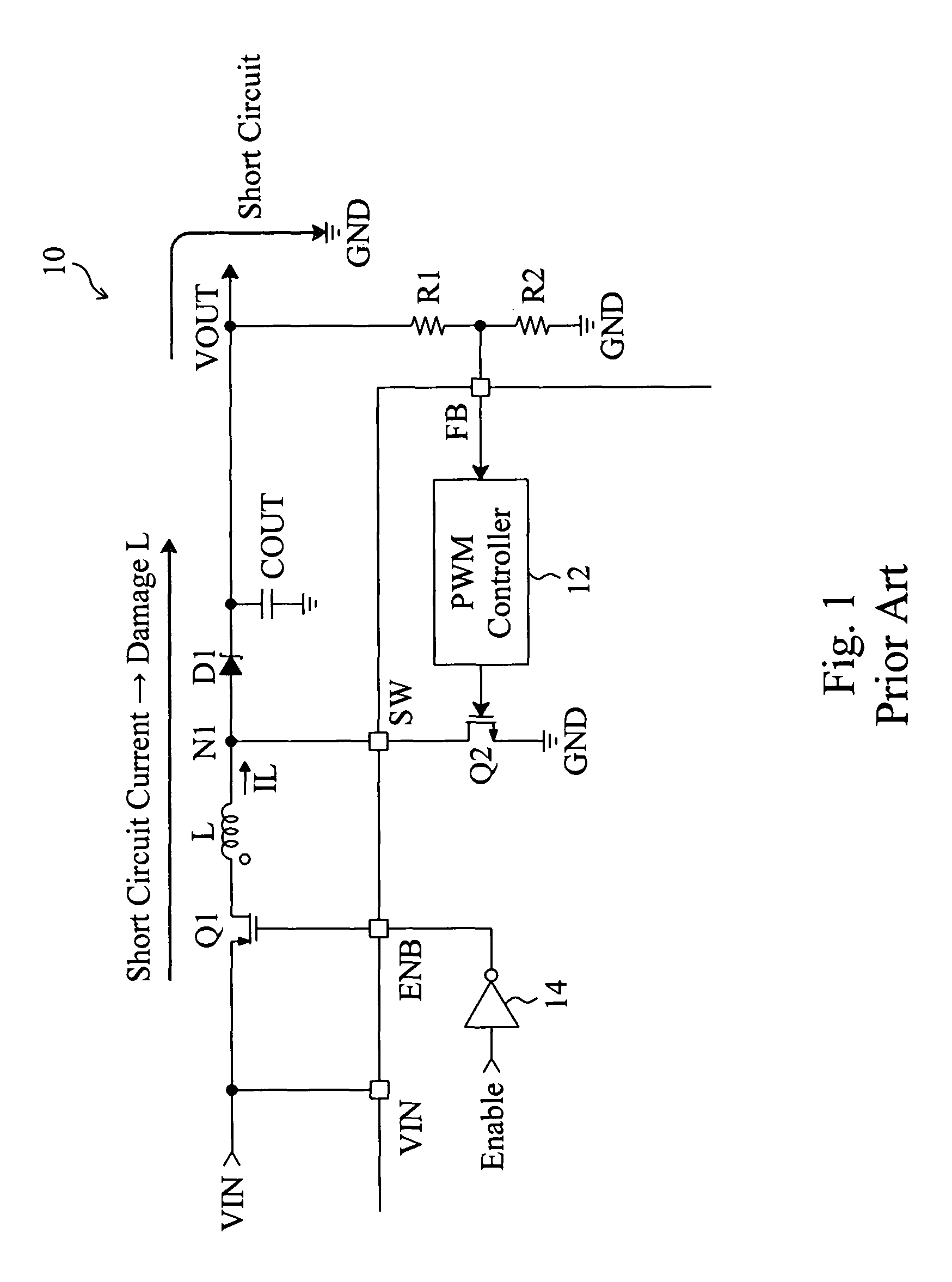
At the moment the boost converter 10 starts up, the output voltage VOUT is zero and therefore a large inductor current IL will be instantly produced that charges the output capacitor COUT, resulting in a huge inrush.
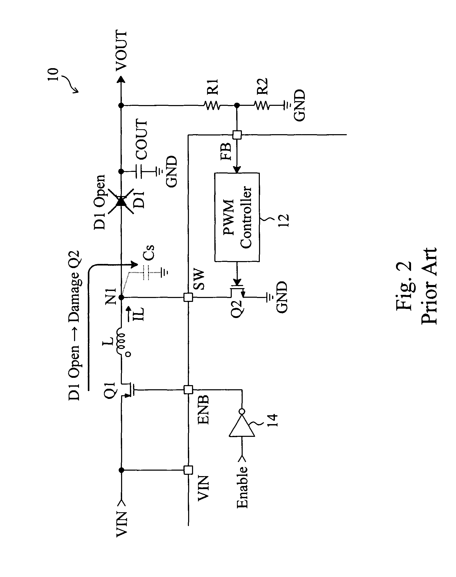
On the other hand, some components of the boost converter 10 may become short circuit or open circuit, thereby damaging certain components.
Because the stray capacitance Cs is very small, the voltage at the switching node N1 may be raised instantly to a very high level and thus damage the power switch Q2.

Method used


Image

  • Short circuit and open circuit protection for a boost converter
  • Short circuit and open circuit protection for a boost converter
  • Short circuit and open circuit protection for a boost converter

Examples


Embodiment Construction

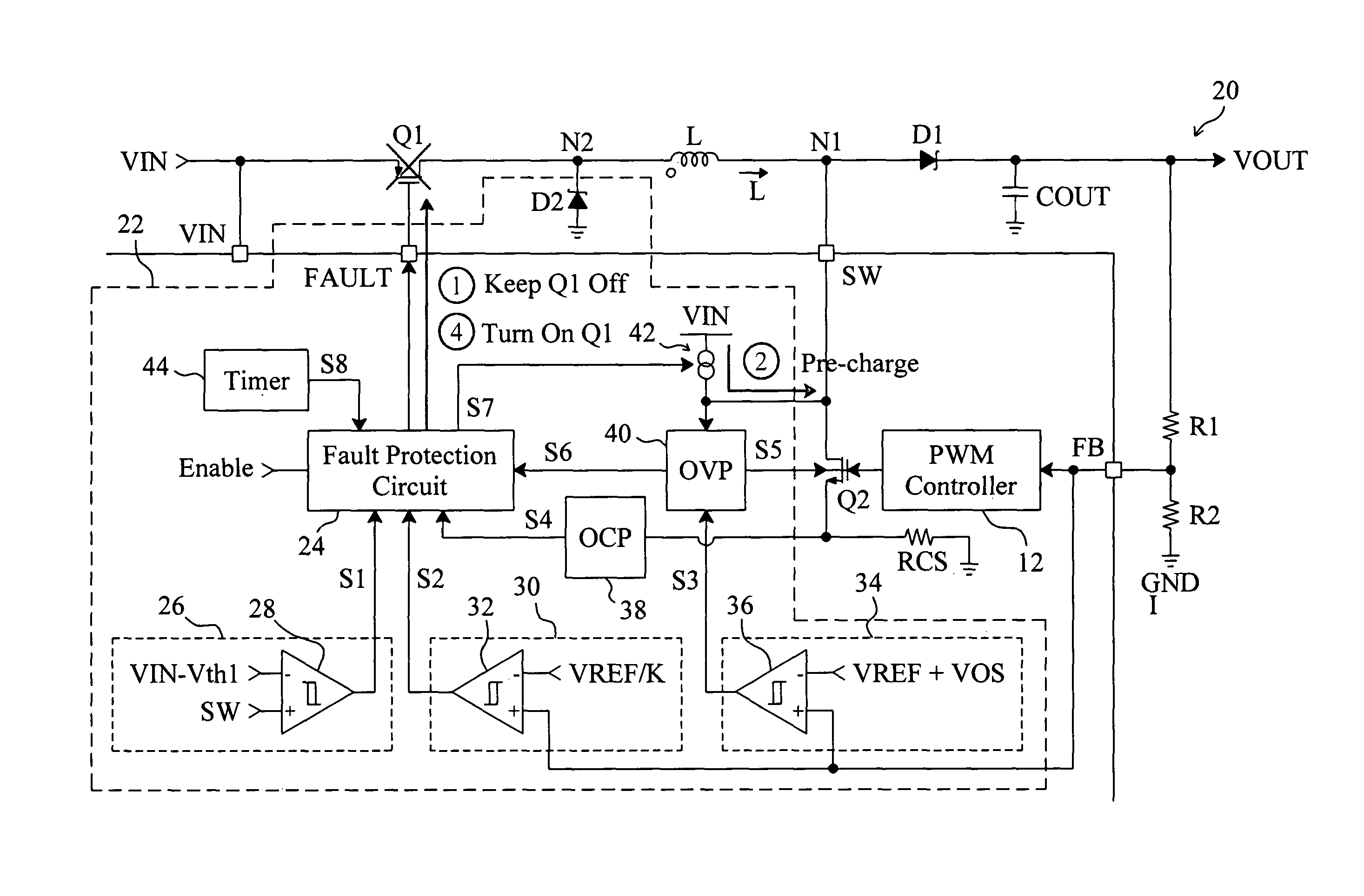
[0026]FIG. 3 is a circuit diagram of an embodiment according to the present invention based on the conventional boost converter 10 shown in FIG. 1, in which a boost converter 20 includes a protection apparatus 22 to provide open circuit and short circuit protection for the boost converter 20. The protection apparatus 22 monitors the voltage at the switching node N1 and the output voltage VOUT for open circuit and short circuit detection. If open circuit or short circuit is detected, the protection apparatus 22 will turn off the load disconnect switch Q1. The protection apparatus 22 includes a fault protection circuit 24 connected to the load disconnect switch Q1 to switch the load disconnect switch Q1. The voltage at the switching node N1 is monitored by monitoring the voltage of the switching pin SW which is connected to the switching node N1, and the output voltage VOUT is monitored by monitoring the feedback voltage FB produced by the voltage divider composed of resistors R1 and ...


PUM


Abstract

A boost converter includes a load disconnect switch connected between a voltage input terminal and an inductor, a power switch connected to the inductor by a switching node, a diode connected between the switching node and a voltage output terminal, and an output capacitor connected to the voltage output terminal to provide an output voltage. A protection apparatus is connected to the load disconnect switch, switching node and power switch to monitor the voltage at the switching node and the output voltage to provide open circuit and short circuit protection for the boost converter.

Description

FIELD OF THE INVENTION[0001]The present invention is related generally to boost converters and, more particularly, to short circuit and open circuit protection for a boost converter.BACKGROUND OF THE INVENTION[0002]As shown in FIG. 1, a conventional boost converter 10 includes a load disconnect switch Q1 connected between a voltage input terminal VIN and an inductor L, a diode D1 connected between the inductor L and a voltage output terminal VOUT, a power switch Q2 connected between a switching node N1 and a ground terminal GND, an output capacitor COUT connected to the voltage output terminal VOUT, and voltage divider resistors R1 and R2 serially connected between the voltage output terminal VOUT and ground terminal GND to divide an output voltage VOUT to provide a feedback voltage FB, and a pulse width modulation (PWM) controller 12 switches the power switch Q2 according to the feedback voltage FB. When the boost converter 10 starts up, an enable signal Enable turns on the load di...

Claims


Application Information

Patent Timeline
Patent Type & Authority Patents(United States)
IPC IPC(8): H02H3/20H02H9/04
CPCH02H7/1213H02M3/156H02M1/36H02M1/32
Inventor LIN, SHUI-MULIU, TI-TIYANG, HUAN-CHIEN
Owner RICHTEK TECH
Learn More