
Lane determining device and navigation system

a technology of determining device and lane, which is applied in the direction of television system, navigation instrument, etc., can solve the problems of difficult to determine the lane the host vehicle is traveling, low estimation accuracy of the position of the host vehicle, and inability to provide differentiated route guidance per lane, etc., to achieve the effect of accurately determining the lane and quick and accurate determining the lan

Active Publication Date: 2013-01-29
CLARION CO LTD
View PDF15 Cites 12 Cited by
  • Summary
  • Abstract
  • Description
  • Claims
  • Application Information

AI Technical Summary

Benefits of technology

The present invention is about a device that can quickly and accurately determine which lane a vehicle is driving on. This is important because the device takes into account the road geometry, so it is able to accurately determine which lane to drive on even when changing lanes on a curved road. The device uses autonomous navigation to guide the vehicle along its destination.

Problems solved by technology

With conventional navigation systems, the estimation accuracy for the host vehicle position was low, and it was difficult to determine the lane the host vehicle is traveling in with respect to roads having a plurality of lanes with the same direction of traffic, that is, so-called roads with a plurality of lanes in each direction.
As such, in giving directions for forks in highways, or in giving directions on which way to go at intersections, differentiated route guidance per lane could not be provided, and it was difficult to improve passenger comfort.

Method used


Image

  • Lane determining device and navigation system
  • Lane determining device and navigation system
  • Lane determining device and navigation system

Examples


Embodiment Construction

[0032]Embodiments are described in detail below with reference to the drawings.

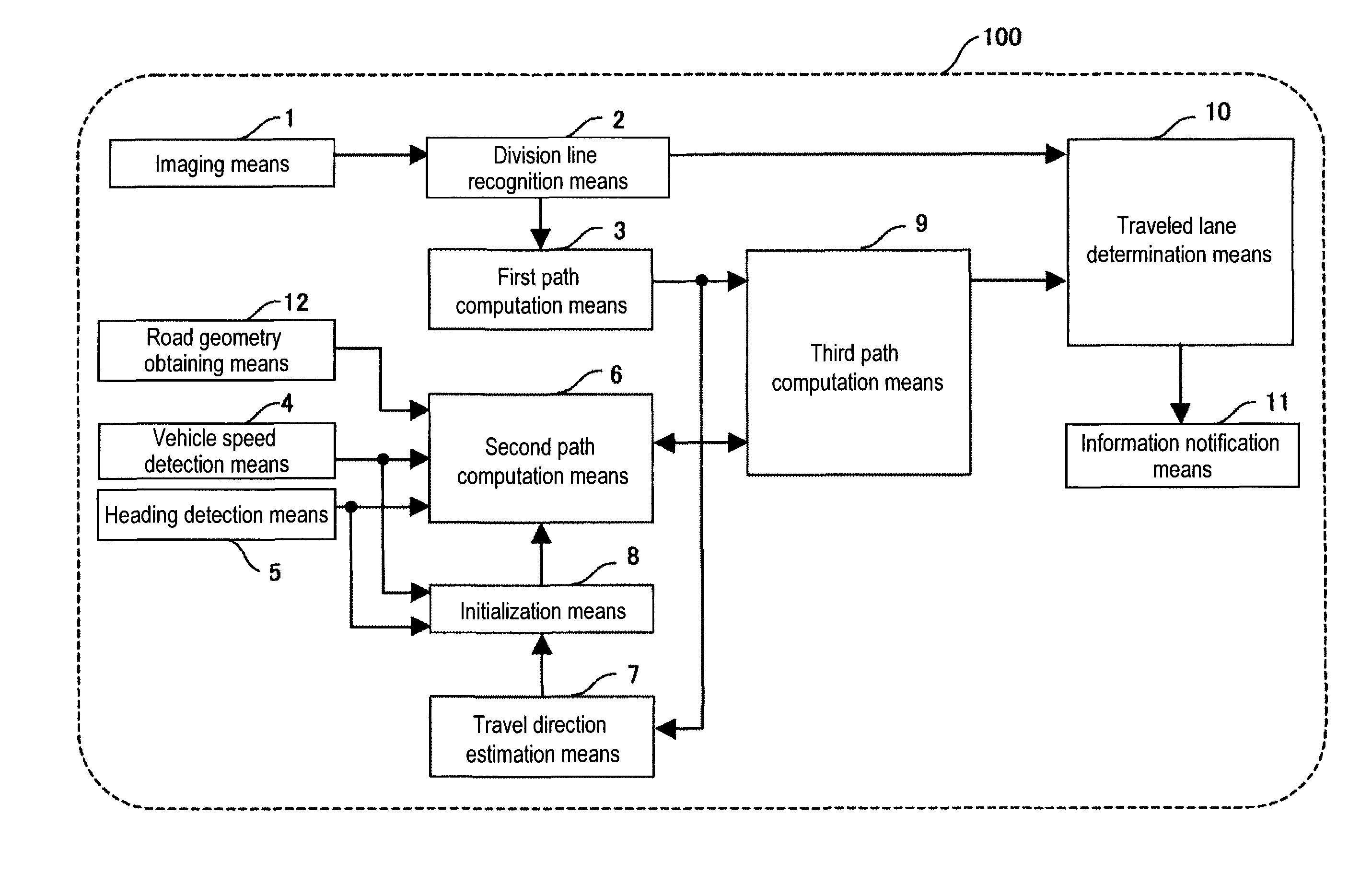
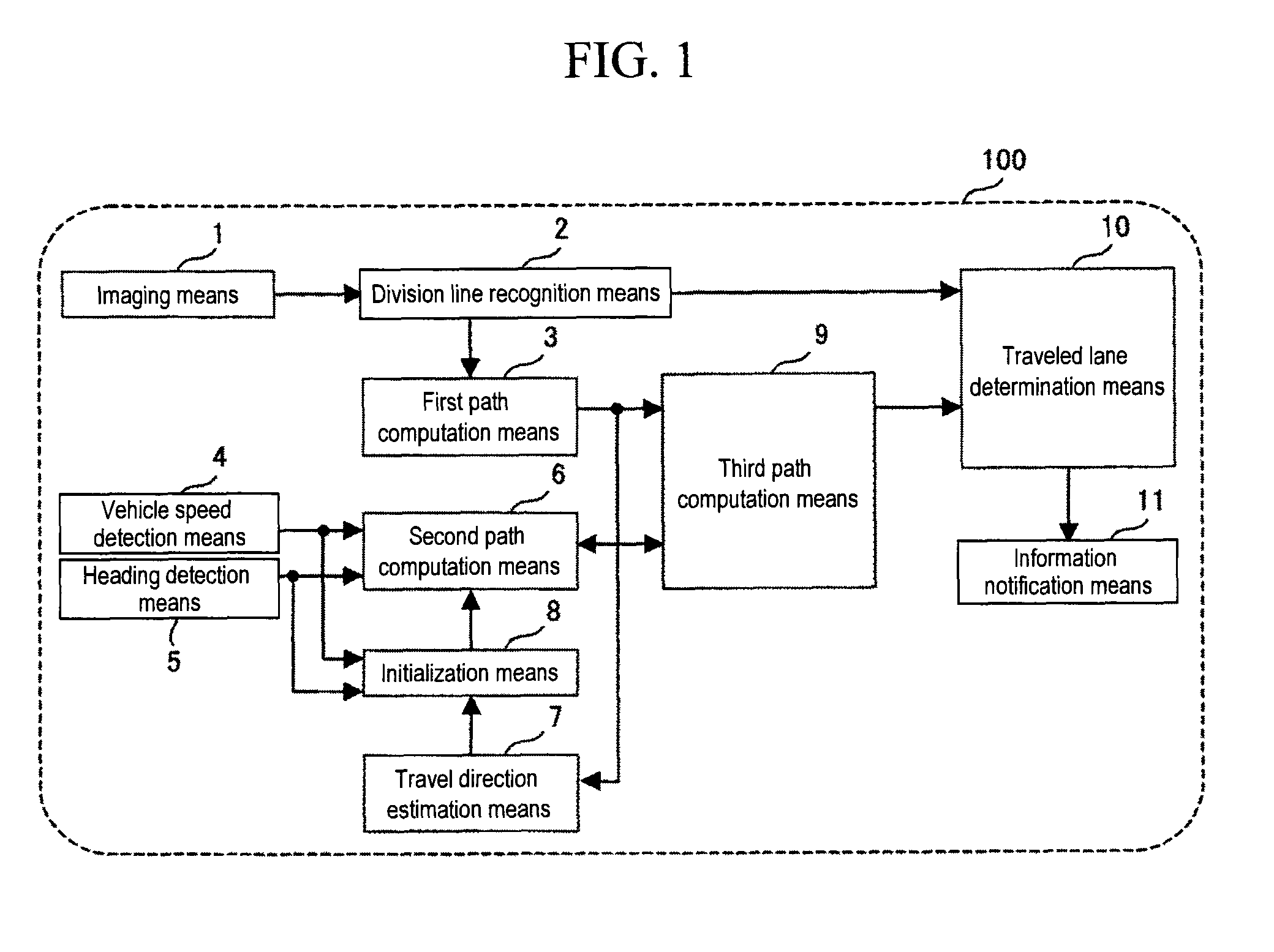
[0033]FIG. 1 is a block diagram showing the functions of a lane determining device.

[0034]First, the configuration and content of processing of a lane determining device 100 will be described.

[0035]The lane determining device 100 comprises: an imaging means 1; a division line recognition means 2; a first path computation means 3; a vehicle speed detection means 4; a heading detection means 5; a second path computation means 6; a travel direction estimation means 7; an initialization means 8; a third path computation means 9; a traveled lane determination means 10; and an information notification means 11. The lane determining device 100 is programmed into a computer, which is not shown in the diagram, of the lane determining device 100 and repeatedly executed with a predefined period.

[0036]The imaging means 1 obtains an image outside of the host vehicle by means of an imaging device such as a CCD (Charge C...


PUM


Abstract

Provided is a lane determining device that is capable of quickly and accurately determining the lane traveled by a host vehicle traveling on a road with a plurality of lanes in each direction. A lane determining device that determines the lane traveled by the host vehicle traveling on a road with a plurality of lanes in each direction comprises: road geometry obtaining means that obtains road geometry; imaging means that images the road; division line recognition means that recognizes a division line from an image imaged by the imaging means; first path computation means that computes a path of the host vehicle by repeatedly computing a distance from the division line recognized by the division line recognition means to the imaging means; second path computation means that computes a path of the host vehicle based on the road geometry obtained by the road geometry obtaining means and on autonomous navigation; third path computation means that computes a path of the host vehicle based on a first path computed by the first path computation means and on a second path computed by the second path computation means; and traveled lane determination means that determines the lane traveled by the host vehicle based on a third path computed by the third path computation means.

Description

TECHNICAL FIELD[0001]The present invention relates to a lane determining device and navigation system that determines the lane a host vehicle is traveling in.BACKGROUND ART[0002]Navigation systems mounted in vehicles have the function of displaying, along with map information of its surroundings, a host vehicle position that is detected by such autonomous methods as a GPS (Global Positioning System), a gyrosystem, etc.[0003]Further, positional accuracy becomes higher the closer the host vehicle position displayed on the navigation system is to the actual host vehicle position. By outputting highly accurate host vehicle positions, passengers are able to obtain appropriate road information with respect to the actual host vehicle position, and it is possible to improve passenger comfort.[0004]With conventional navigation systems, the estimation accuracy for the host vehicle position was low, and it was difficult to determine the lane the host vehicle is traveling in with respect to roa...

Claims


Application Information

Patent Timeline
Patent Type & Authority Patents(United States)
IPC IPC(8): H04N7/18
CPCB60W30/12G08G1/167G08G1/16G01C21/3658
Inventor IMAI, MASATOHOSHINO, MASATOSHISAKATA, MASAO
Owner CLARION CO LTD
Learn More