Multi-stage sliding structure of handheld device

a handheld device and multi-stage technology, applied in the direction of sliding contact bearings, mechanical energy handling, mechanical apparatus, etc., can solve the problems of easy wear of flanges and ribs, increased cost, and increased cost, so as to reduce cost, simplify manufacturing process, and avoid elastic fatigue

Inactive Publication Date: 2013-01-29
INVENTEC APPLIANCES CORP
View PDF7 Cites 2 Cited by
  • Summary
  • Abstract
  • Description
  • Claims
  • Application Information

AI Technical Summary

Benefits of technology

[0011]Accordingly, the present invention is directed to a sliding structure, which is capable of stably stopping at different positions when a sliding cover is sliding on a main body of a mobile phone, does not require complicated manufacturing processes, lowers the cost, and has high durability.
[0020]Firstly, through the magnetic repulsion / attraction between the first and the second magnetic strips, when the first and the second sliding blocks slide with respect to each other, the length of the magnetic strips can be designed to allow the first sliding block to stop at different specific positions. Thus, the elastic element is not needed, and elastic fatigue can be avoided.
[0021]Secondly, through the magnetic repulsion / attraction between the first and the second magnetic strips, the purpose of multi-stage stop can be achieved, such that there is no need to configure flanges and ribs on the slide rail of the sliding structure. Thus, in the structure forming, the manufacturing process is simplified, and the cost is lowered. Besides, the abrasion of the flanges and ribs is avoided.
[0022]Thirdly, the magnetic strips can be designed in accordance with the sliding mode of the two sliding blocks, and compared with the elastic elements (for example, springs), the magnetic strips are smaller in volume and area. Thus, the handheld device is made even thinner. Moreover, other components or functional modules like circuits or antennas can be configured to further improve the applicability of the handheld device.

Problems solved by technology

Firstly, despite its configuration, the elastic element has a certain elastic durability. Once exceeding the durability, the main body of the mobile phone will be loosened from its cover, and the sliding cover cannot stop at a specific position. Besides, the serpentine or S-shaped bends definitely increase the material required to form the elastic element, and thus the cost will rise.
Secondly, if the slidable mobile phone requires additional multi-stage sliding, flanges and ribs need to be designed on the slide rail of the sliding structure of the mobile phone. Thus, for the shell molding operation, a complicated process needs to be added, and the cost is increased. Moreover, the flanges and ribs are easily worn, such that the cover of the mobile phone is difficult to slide and stop at a specific position.

Method used


Image

  • Multi-stage sliding structure of handheld device
  • Multi-stage sliding structure of handheld device
  • Multi-stage sliding structure of handheld device

Examples


first embodiment

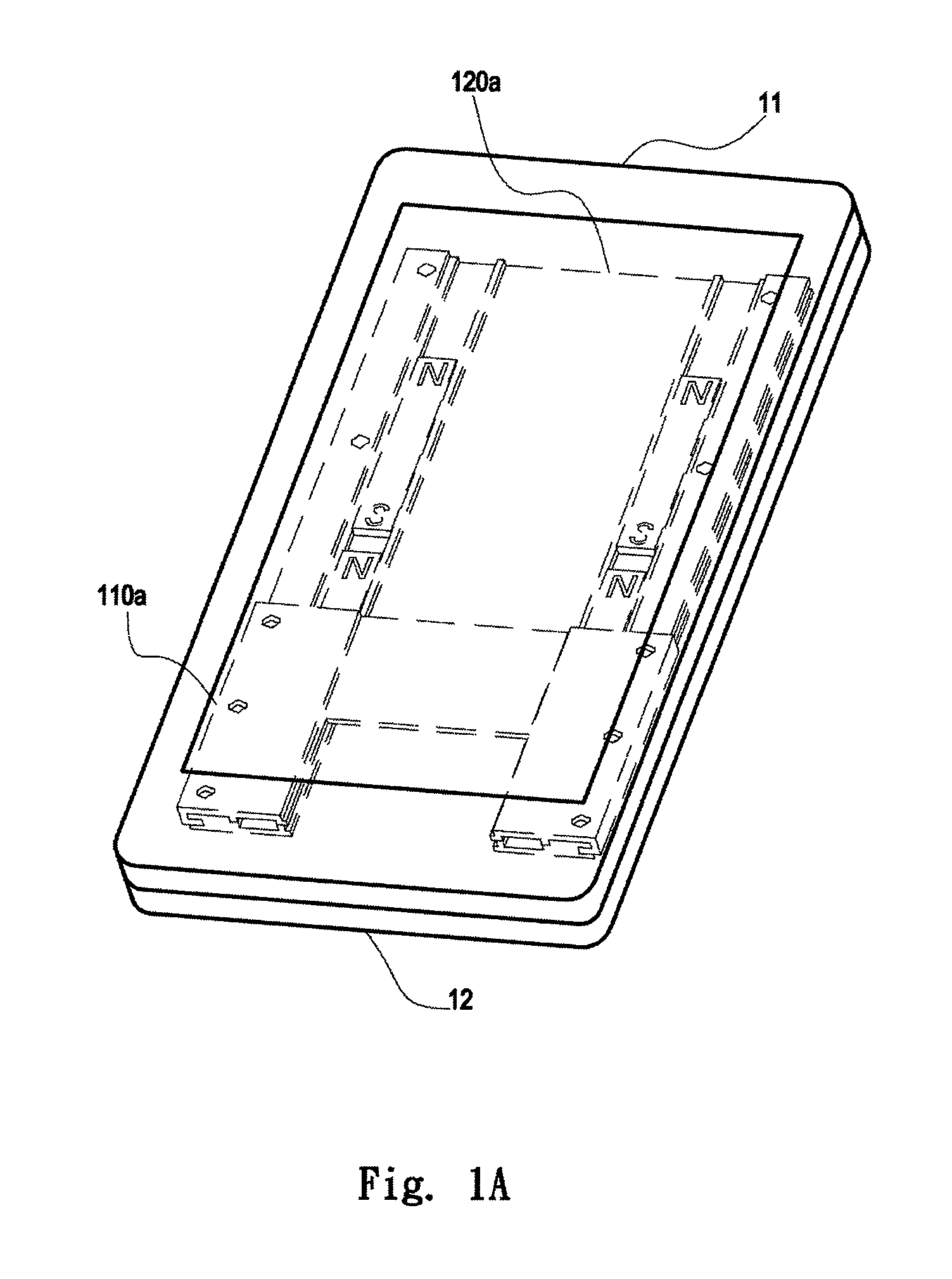
[0047]FIG. 2 is a graphical picture showing the first sliding block 110a stops at a first position 141a according to the present invention.

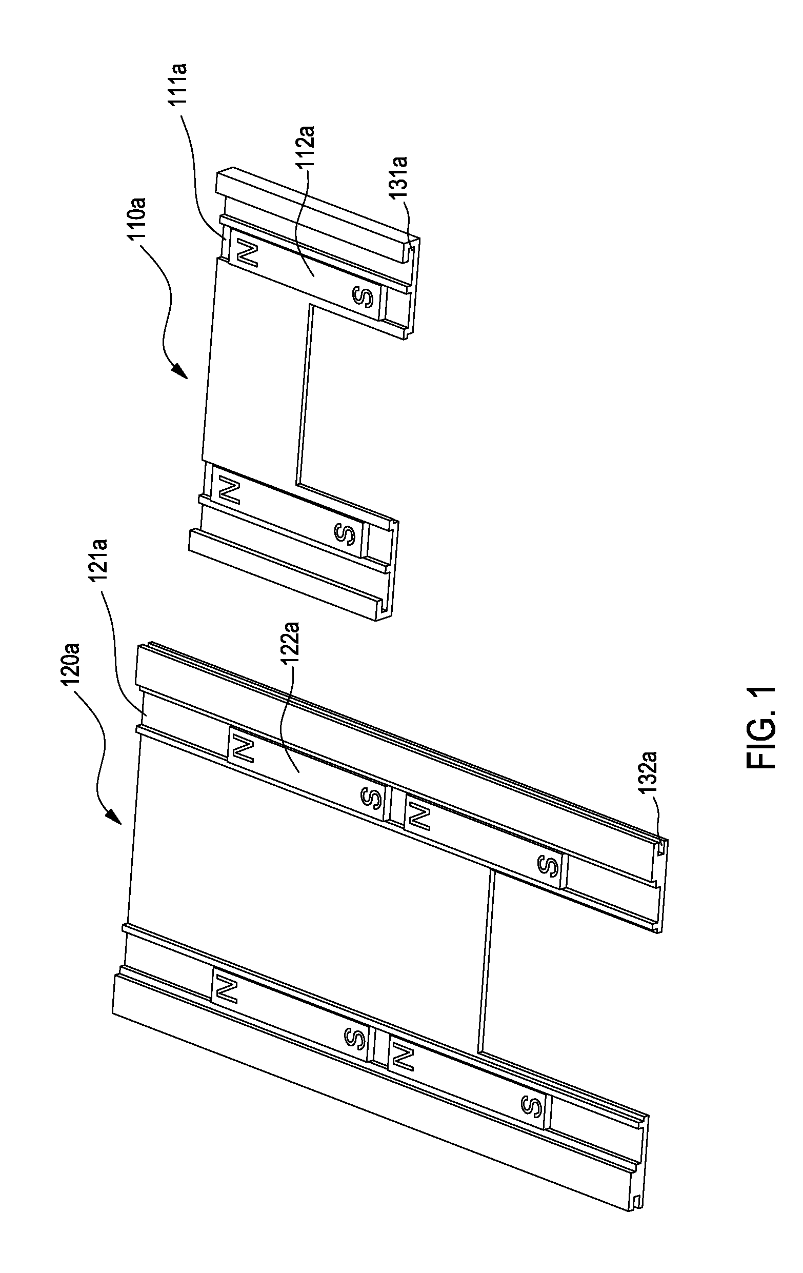
[0048]In each second groove 121a of the second sliding block 120a, there is unoccupied space between the opening at the top end of the second groove 121a and a top end of the second magnetic strip 122a on the upper side adjacent to the opening. When the first sliding block 110a slides to the first position 141a, the positions of the N-poles of the two first magnetic strips 112a are corresponding to the two unoccupied spaces connecting to the top openings of the two second grooves 121a, respectively. In this case, by way of repulsion between the same magnetic poles, the N-poles of the second magnetic strips 122a on the upper side repel or push against the N-poles of the first magnetic strips 112a respectively. Meanwhile, the S-poles of the second magnetic strips 122a on the upper side repel or push against the S-poles of the first magnetic strips ...

second embodiment

[0063]FIG. 6 is a graphical picture of the sliding movement of the sliding structure according to the present invention.

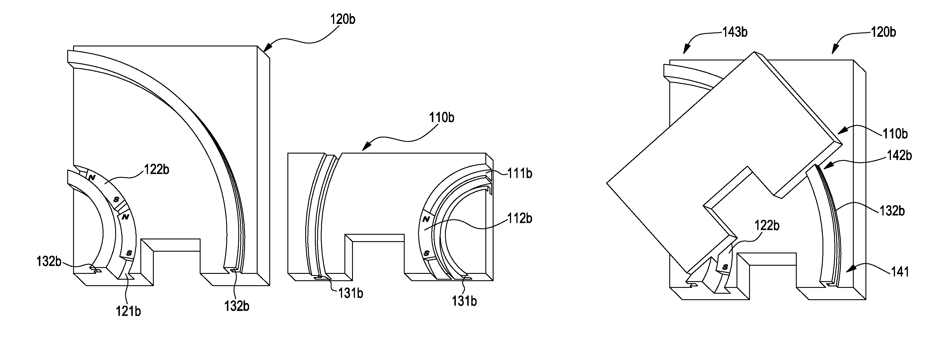
[0064]With reference to FIG. 5, in the second groove 121b of the second sliding block 120b, there is unoccupied space between the opening at the left end of the second groove 121b and a top end of the second magnetic strip 122b on the upper side adjacent to the left opening, and there is unoccupied space between the opening at the bottom end of the second groove 121b and a bottom end of the second magnetic strip 122b on the lower side adjacent to the bottom opening. With reference to FIGS. 5 and 6, when the first sliding block 110b slides to a first position 141b, the position of the S-pole of the first magnetic strip 112b is corresponding to the unoccupied space connecting to the bottom opening of the second groove 121b. At this time, by way of repulsion between the same magnetic poles, the N-pole of the second magnetic strip 122b on the lower side in FIG. 5 repel...

third embodiment

[0071]FIG. 8 is a graphical picture showing the first sliding block 110c stops at a first position 141c according to the present invention. Further understandings can be achieved by referring to FIGS. 7 and 8 together.

[0072]When the first sliding block 110c engages with the second sliding block 120c, two end poles of the first magnetic strip 112c can be stably located respectively in two positions corresponding to the spaces between the two second magnetic strips 122c. When the first sliding block 110c is disposed at the first position 141c with respect to the second sliding block 120c, the N-poles of the two second magnetic strips 122c are corresponding to and repel or push against the N-pole of the first magnetic strip 112c. Similarly, the S-poles of the two second magnetic strips 122c are corresponding to and repel or push against the S-pole of the first magnetic strip 112c. Thus, the first sliding block 110c stably stops at the first position 141c in a balance state due to the a...


PUM


Abstract

A multi-stage sliding structure of a handheld device includes a first sliding block, a second sliding block, and an engagement structure. The first sliding block has at least one first groove for containing a first magnetic strip. The second sliding block has at least one second groove. The second groove is for containing at least two second magnetic strips which are continually spaced apart in the second groove, and the directions of magnetic poles of the second magnetic strips correspond with directions of respective magnetic poles of the first magnetic strip. The engagement structure includes two structures disposed near outer sides of the first and the second grooves respectively, and is for enabling the first and the second sliding blocks to engage with each other and slide with respect to each other.

Description

CROSS-REFERENCE TO RELATED APPLICATION[0001]This application claims the benefit of Taiwan utility model application No. 097216471, filed on Sep. 12, 2008, which is hereby incorporated by reference for all purposes as if fully set forth herein.BACKGROUND OF THE INVENTION[0002]1. Field of Invention[0003]The present invention relates to a sliding structure of a handheld device, and more particularly to a multi-stage sliding structure of a handheld device that provides an advantage of multi-stage sliding from the magnetic attraction / repulsion.[0004]2. Related Art[0005]In the prior art, for example, Taiwan, R.O.C. Patent Publication No. M285859 discloses a slidable hinge structure mounted on a handheld electronic device. The slidable hinge structure is formed by a main body and a sliding cover disposed thereon.[0006]The slidable hinge includes a base fixed on the main body and a sliding seat fixed on the sliding cover. The sliding seat is slidably disposed on the base. At least one strip...

Claims


Application Information

Patent Timeline
Patent Type & Authority Patents(United States)
IPC IPC(8): H04M1/00
CPCH04M1/0237
Inventor JIN, WEIWEN, MING
Owner INVENTEC APPLIANCES CORP
Why Eureka
Try Eureka