
Displacement/distortion measuring method and displacement/distortion measuring apparatus

a technology of displacement/distortion and measuring method, which is applied in the direction of instruments, material analysis through optical means, optical elements, etc., can solve the problems of troublesome installation and maintenance of the measuring apparatus, the inability of the proposed method to realize high-precision displacement measurement and strain measurement, and the difficulty of constant environmental conditions, such as illumination, in the measurement method using a ccd camera

Inactive Publication Date: 2013-01-01
SMART STRUCTURES LLC
View PDF11 Cites 0 Cited by
  • Summary
  • Abstract
  • Description
  • Claims
  • Application Information

AI Technical Summary

Benefits of technology

The present invention provides a simple and high-precision method for measuring displacement and strain using a line scanner apparatus. The line scanner apparatus can capture high-resolution images without the need for adjusting illumination, ensuring consistent measurement results. Additionally, the portability of a notebook personal computer allows for easy measurement at any location.

Problems solved by technology

The measuring method using a strain gauge however has problems such that installation and maintenance of the measuring apparatus are troublesome, and are not suitable for minute areas or irregular portions.
Since both methods calculate the amount of displacement or strain based on a plurality of digital images picked up by a CCD camera, they have the following problem, and methods proposed so far cannot realize high-precision displacement measurement and strain measurement.
That is, a measuring method using a CCD camera has (1) a difficulty in always keeping the environmental conditions, such as illumination, constant.
(3) Even execution of aberration correction of the camera lens becomes a large error factor.

Method used


Image

  • Displacement/distortion measuring method and displacement/distortion measuring apparatus
  • Displacement/distortion measuring method and displacement/distortion measuring apparatus
  • Displacement/distortion measuring method and displacement/distortion measuring apparatus

Examples


Embodiment Construction

[0045]An embodiment of the present invention will now be described with reference to the accompanying drawings.

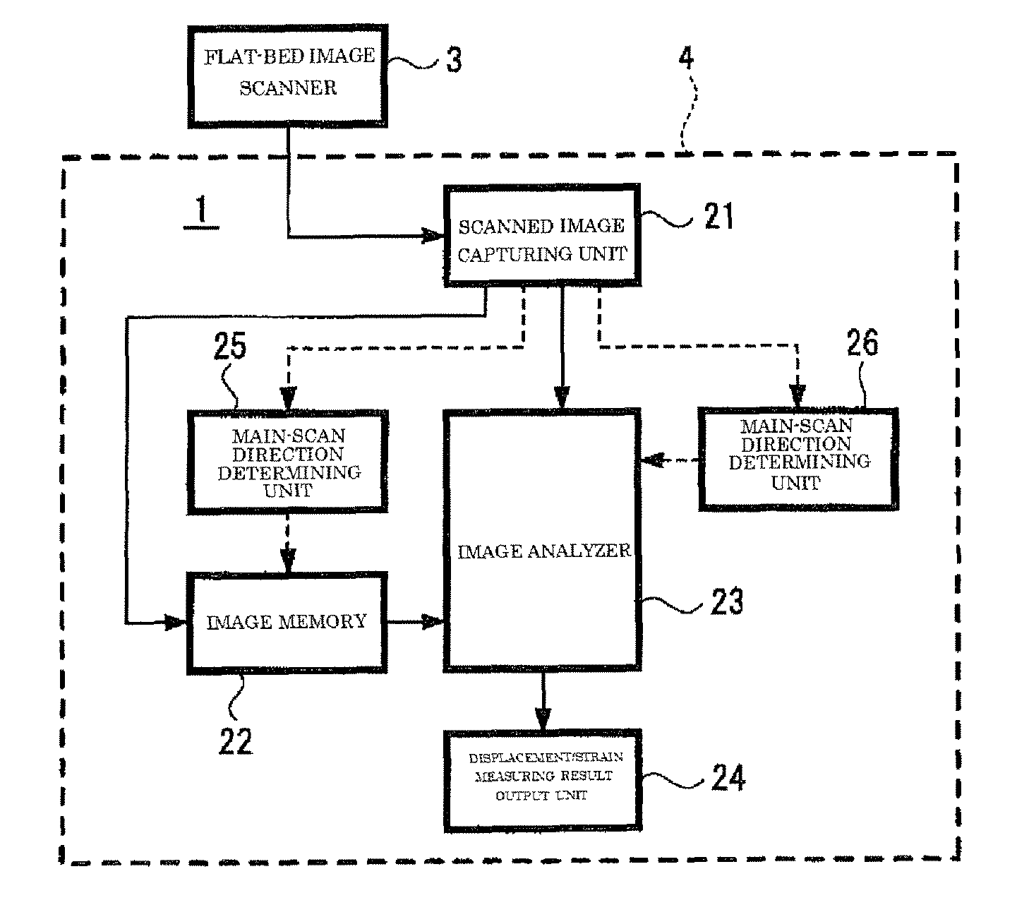
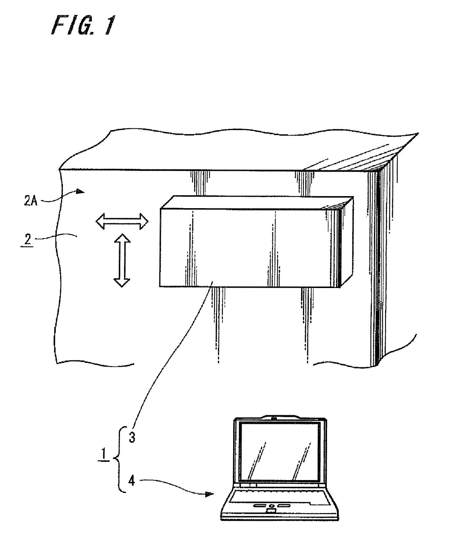
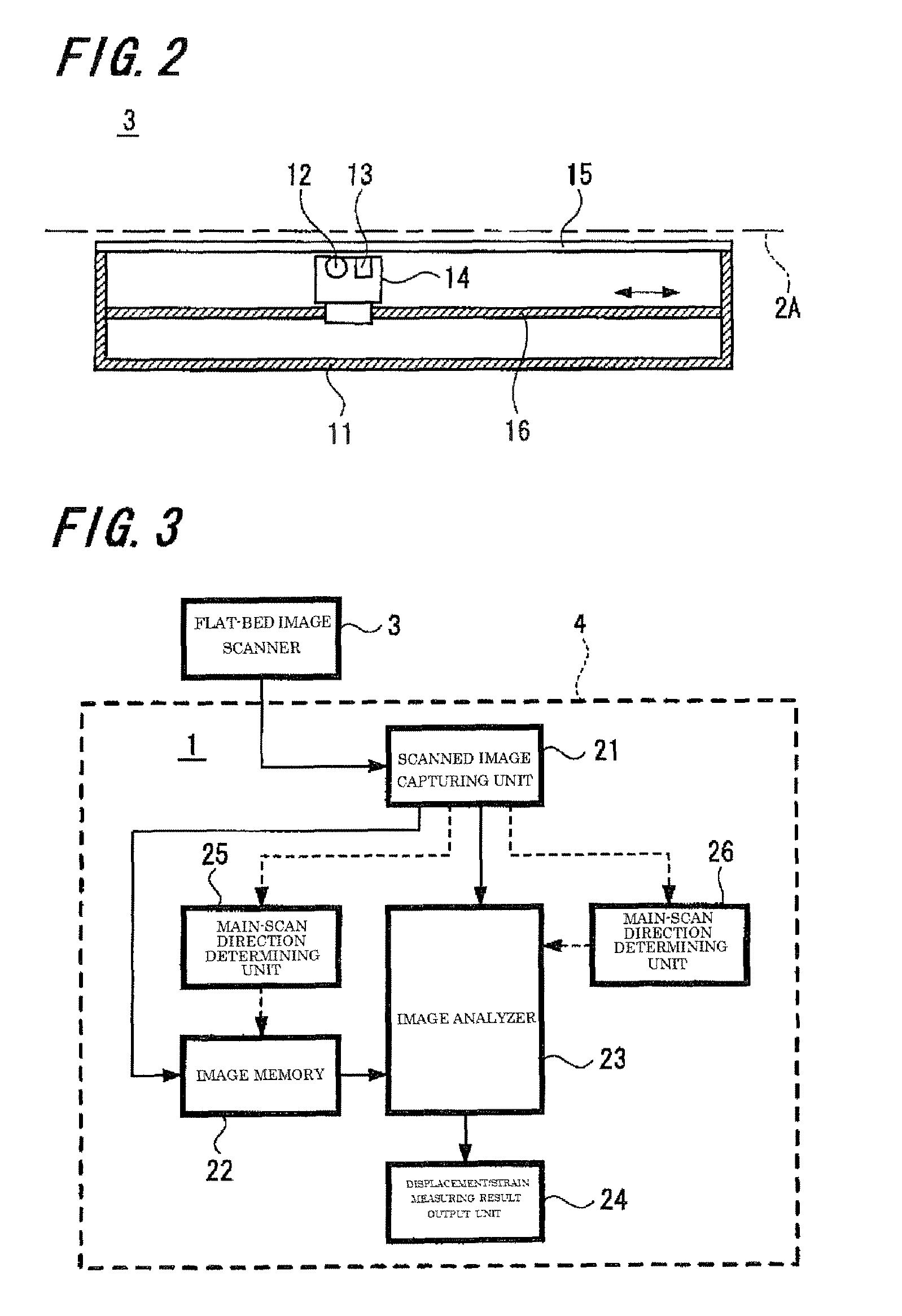
[0046]FIGS. 1 and 2 shows the schematic configuration of a displacement / strain measuring apparatus to be adapted to a displacement / strain measuring method according to the present invention. A displacement / strain measuring apparatus 1 according to the embodiment comprises a contact line scanner apparatus typified by a flat-bed image scanner for imaging a top surface 2A of an object 2 to be measured, e.g., the surface of a concrete structure, namely a flat-bed image scanner 2 in the embodiment, and a computer or a personal computer 4 in the embodiment, which executes a sequence of processes of capturing the image of the top surface of a to-be-measured object imaged by the flat-bed image scanner 3, measuring a displacement or strain of the to-be-measured object from the image through image analysis, and outputting the measuring result. Image analysis is carried out from an im...


PUM

PropertyMeasurementUnit
sizeaaaaaaaaaa
grain sizeaaaaaaaaaa
angleaaaaaaaaaa

Abstract

Provided are a displacement / distortion measuring method and a displacement / distortion measuring apparatus for easily and highly accurately measuring displacement or distortion of an object. An image of the surface of the measuring object is picked up by a line scanner apparatus adhered or brought close to the surface of the measuring object. The image is taken, displacement or distortion is measured by image analysis of the image of the measuring object surface prior to time lapse and that after time lapse, and displacement or distortion measuring results are outputted.

Description

TECHNICAL FIELD[0001]The present invention relates to a displacement / strain measuring method and displacement / strain measuring apparatus, which measure the displacement or strain of an object.BACKGROUND ART[0002]To secure safety of an apparatus, equipment, and a structure, such as an iron bridge or concrete structure, it is necessary to grasp the states, such as stress, strain and deformation from the design phase to the in-service phase. For example, hard and fragile materials, such as concrete or ceramics, unlike an elastoplastic material like a metal material, have a small deformation range until cracking, which is a phenomenon of a “minute strain area” of several hundred micro stain order, thus requiring a relatively high-precision measurement. Conventionally, the main stream of the method of measuring stress, strain and deformation is local measurement using a strain gauge. A strain gauge is configured to have a thin metal wire to be a resistor disposed in a folded state in an ...

Claims


Application Information

Patent Timeline
Patent Type & Authority Patents(United States)
IPC IPC(8): G03F3/08G06K9/00G06K15/00G02B27/42G01B11/14
CPCG01B11/16
Inventor MATSUDA, HIROSHIUCHINO, MASAKAZUITO, YUKIHIROYOSHIMARU, KOUSUKEYAMAZAKI, CHIKARAYAMAZAKI, SHUICHIUCHIDA, KOUSUKE
Owner SMART STRUCTURES LLC
Learn More