
System and method for inspecting the interior surface of a pipeline

a pipeline and inspection system technology, applied in the field of visual inspection, can solve the problems of not providing an accurate measure of a defect, the described system is quite complex to implement, and the heavy duty of the system is not enough, so as to achieve accurate and reliable measurements and accurate results

Inactive Publication Date: 2013-01-01
9022 5582 QUEBEC INC C TEC
View PDF15 Cites 9 Cited by
  • Summary
  • Abstract
  • Description
  • Claims
  • Application Information

AI Technical Summary

Benefits of technology

[0012]Advantageously, the inspection system of the present invention provides accurate and reliable measures of the defects, and more particularly of the width of a longitudinal crack, thereby allowing to classify the localised defect according to industry standards.
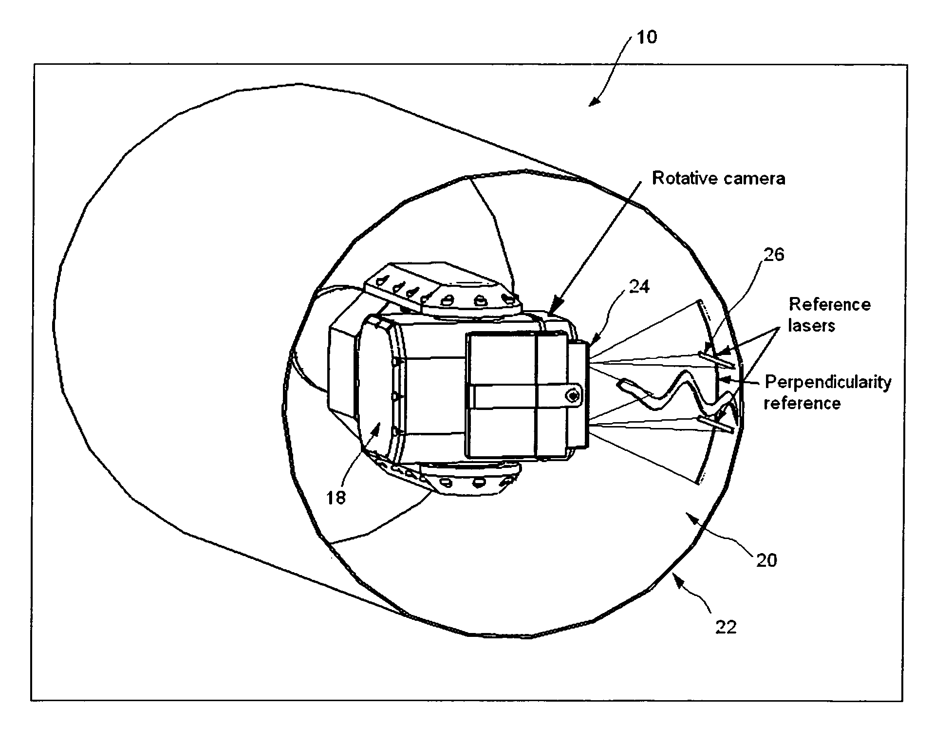
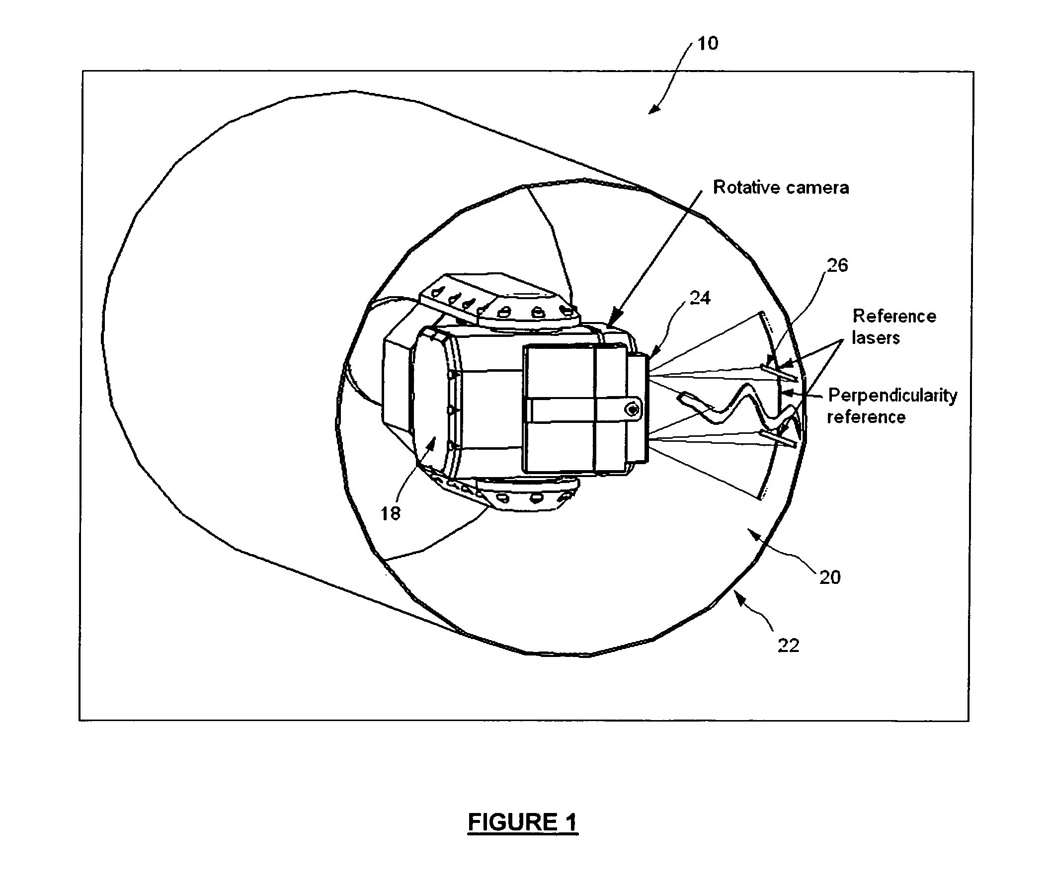
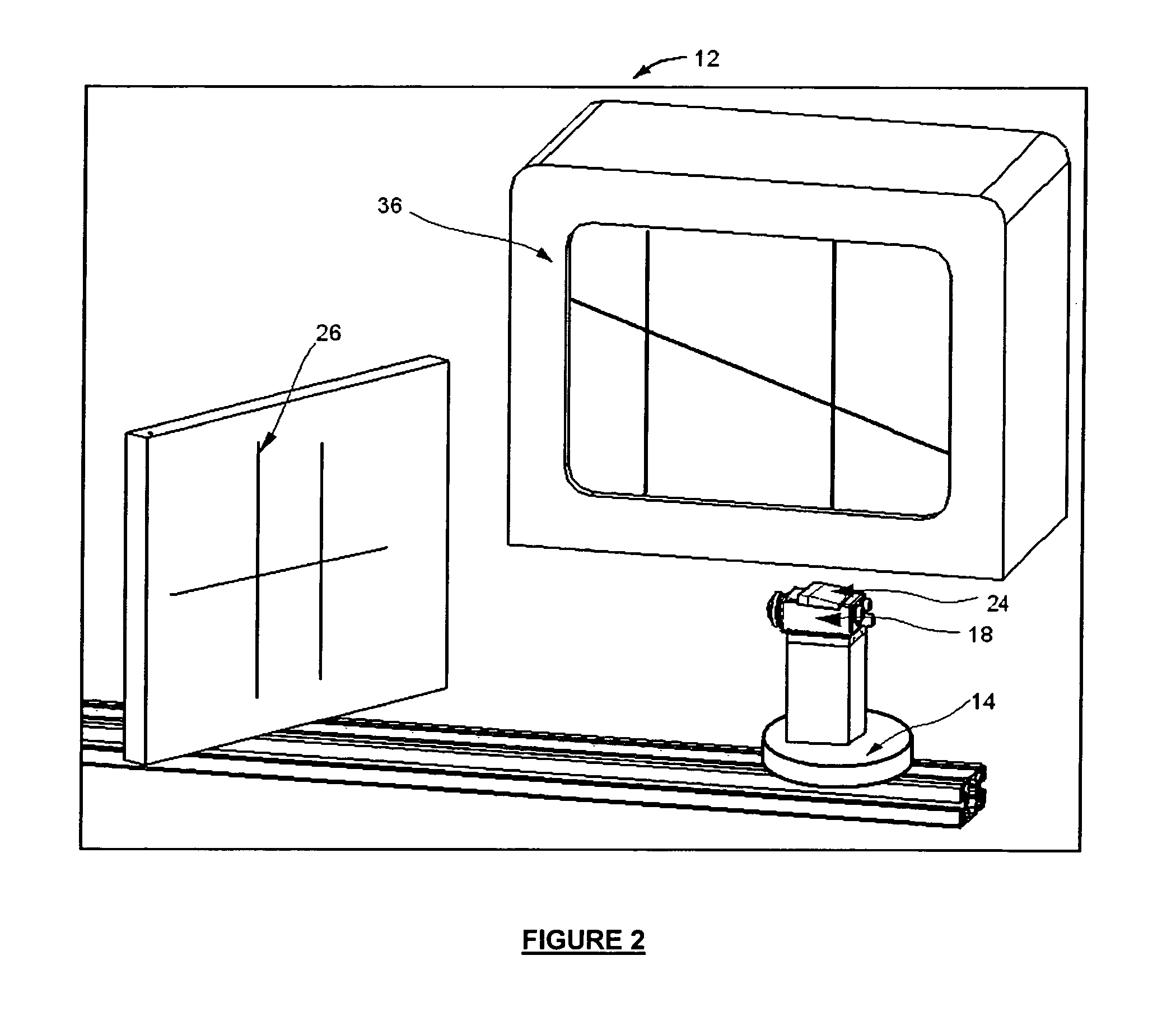
[0013]In a preferred embodiment, the inspection system has a processing unit for processing at least one of the images to determine the width of a longitudinal crack. The processing unit is further adapted to calibrate the inspection system responsively to the shape of the two-dimensional pattern projection for still providing accurate measures even if the optical axis of the imaging means does not extend perpendicularly to the selected portion of the interior surface under inspection.

Problems solved by technology

These inspection systems are well adapted for a coarse visual inspection but can not provide an accurate measure of a defect such as the precise width of the crack at particular point.
The described system is however quite complex to implement and not enough heavy-duty, especially for a specific use in small underground sewage pipes.
These systems do not however provide accurate and reliable measures of the defects.

Method used


Image

  • System and method for inspecting the interior surface of a pipeline
  • System and method for inspecting the interior surface of a pipeline
  • System and method for inspecting the interior surface of a pipeline

Examples


Embodiment Construction

[0029]In the following description, similar features in the drawings have been given similar reference numerals and in order to weight down the figures, some elements are not referred to in some figures if they were already identified in a precedent figure.

[0030]The present invention is directed to an inspection system for inspecting the interior surface of a pipeline providing accurate and reliable measures of the detected defects, and more particularly of the width of longitudinal cracks, thereby allowing to classify the localised defects according to industry standards. In a preferred embodiment that will be described below, a precision of the order of the hundredth of millimeter can be obtained.

[0031]The system of the present invention is particularly advantageous over the known prior art device using a camera for imaging the surface under inspection in that it allows to determine the perpendicularity of the optical axis of the camera with respect to the inspected surface prior ...


PUM


Abstract

An inspection system for inspecting an interior surface of a pipeline has a frame adapted to travel in the pipeline and an imaging means for imaging a selected portion of the interior surface of the pipeline. The imaging means has a field of view and is mounted in a rotatable manner on the frame. The inspection system has with a two-dimensional pattern generator for generating a two-dimensional pattern projection. The generator is mounted with the imaging means to project the two-dimensional pattern projection in the field of view thereof. The imaging means provide images of the selected portion of the internal surface comprising the two-dimensional pattern projection for monitoring a perpendicularity of the optical axis of the imaging means with respect to the selected portion of the interior surface of the pipeline thanks to a shape of the two-dimensional pattern projection prior to inspection of the internal surface.

Description

FIELD OF THE INVENTION[0001]The present invention generally relates to the field of visual inspection, and more particularly concerns an inspection system for inspecting the interior surface of a pipeline that provides improved measurements of defects such as the measure of the width of a crack. The invention also provides an inspection method.BACKGROUND OF THE INVENTION[0002]The presence of longitudinal fissures in concrete pipes is a main concern when the time comes to determine the condition of the pipes. According to the standards of the industry, the width of the crack has to be correctly determined in order to classify the defect.[0003]In the art, several tools particularly adapted to provide images of the internal surface of a pipe have been proposed and are currently used. These tools are generally provided with a vehicle adapted to travel in the pipe and an imaging means such as a camera mounted on the vehicle. The vehicle is generally operatively connected to a control uni...

Claims


Application Information

Patent Timeline
Patent Type & Authority Patents(United States)
IPC IPC(8): H04N7/18
CPCG01B11/14G01B11/2513G01N21/892G01N21/954F16L2101/30
Inventor DEMERS, DANIELLEGENDRE, LUDOVICOTIS, FREDERIC
Owner 9022 5582 QUEBEC INC C TEC
Learn More