Eureka AIR delivers breakthrough ideas for toughest innovation challenges, trusted by R&D personnel around the world.

Low profile electrical device assembly

a low-profile, electrical device technology, applied in the direction of coupling device connections, emergency protective arrangements for limiting excess voltage/current, tumbler/rocker switches, etc., can solve the imbalance between the current flowing in the phase and neutral conductor, the opening of both sides of the ac line, and the removal of all power from the ac load. , to achieve the effect of low profil

Active Publication Date: 2013-01-01
HUBBELL INC
View PDF116 Cites 16 Cited by
  • Summary
  • Abstract
  • Description
  • Claims
  • Application Information

AI Technical Summary

Benefits of technology

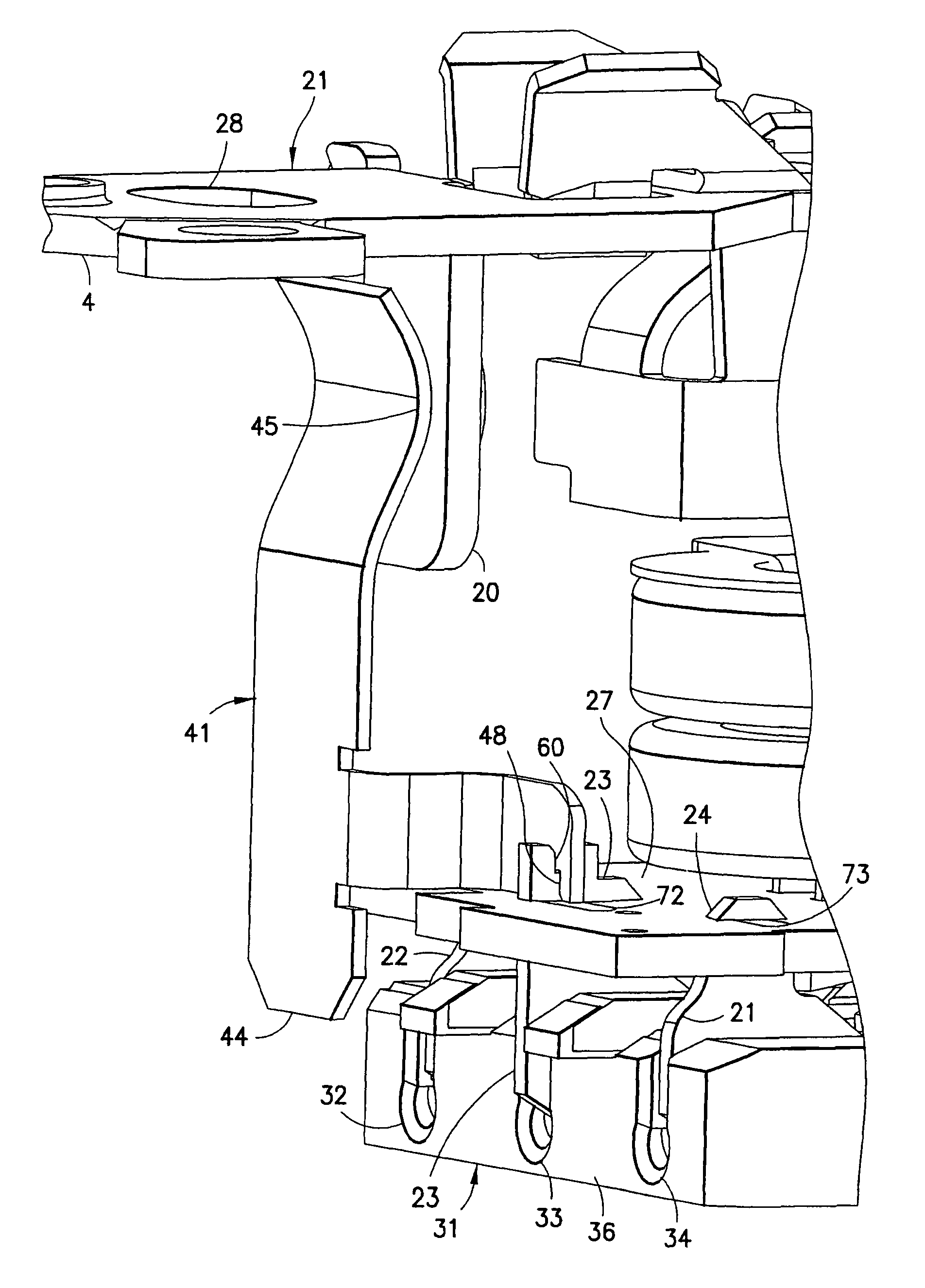
[0009]A still further objective of the present invention is to provide a GFCI device having an improved ground contact member electrically connecting the plug to a ground strap to provide the assembly with a low profile.

Problems solved by technology

Generally, the ground fault condition results when a person or object comes into contact with the line side of the AC load and an earth ground at the same time, a situation which can result in serious injury.
A ground fault condition happens when the current is diverted to the ground through another path, such as a human body, that results in an imbalance between the currents flowing in the phase and neutral conductors.
When such an imbalance is detected, a circuit breaker within the ground fault circuit interrupter is immediately tripped to an open condition, thereby opening both sides of the AC line and removing all power from the AC load.
When a ground fault occurs in the protected circuit, or when the test button is depressed, the GFCI device trips and an internal circuit breaker opens both sides of the AC line.
However, providing a GFCI device with such a plug results in a large and obtrusive device, particularly in view of the plug wires extending perpendicularly with respect to a rear surface of the electrical receptacle.

Method used


Image

  • Low profile electrical device assembly
  • Low profile electrical device assembly
  • Low profile electrical device assembly

Examples


Embodiment Construction

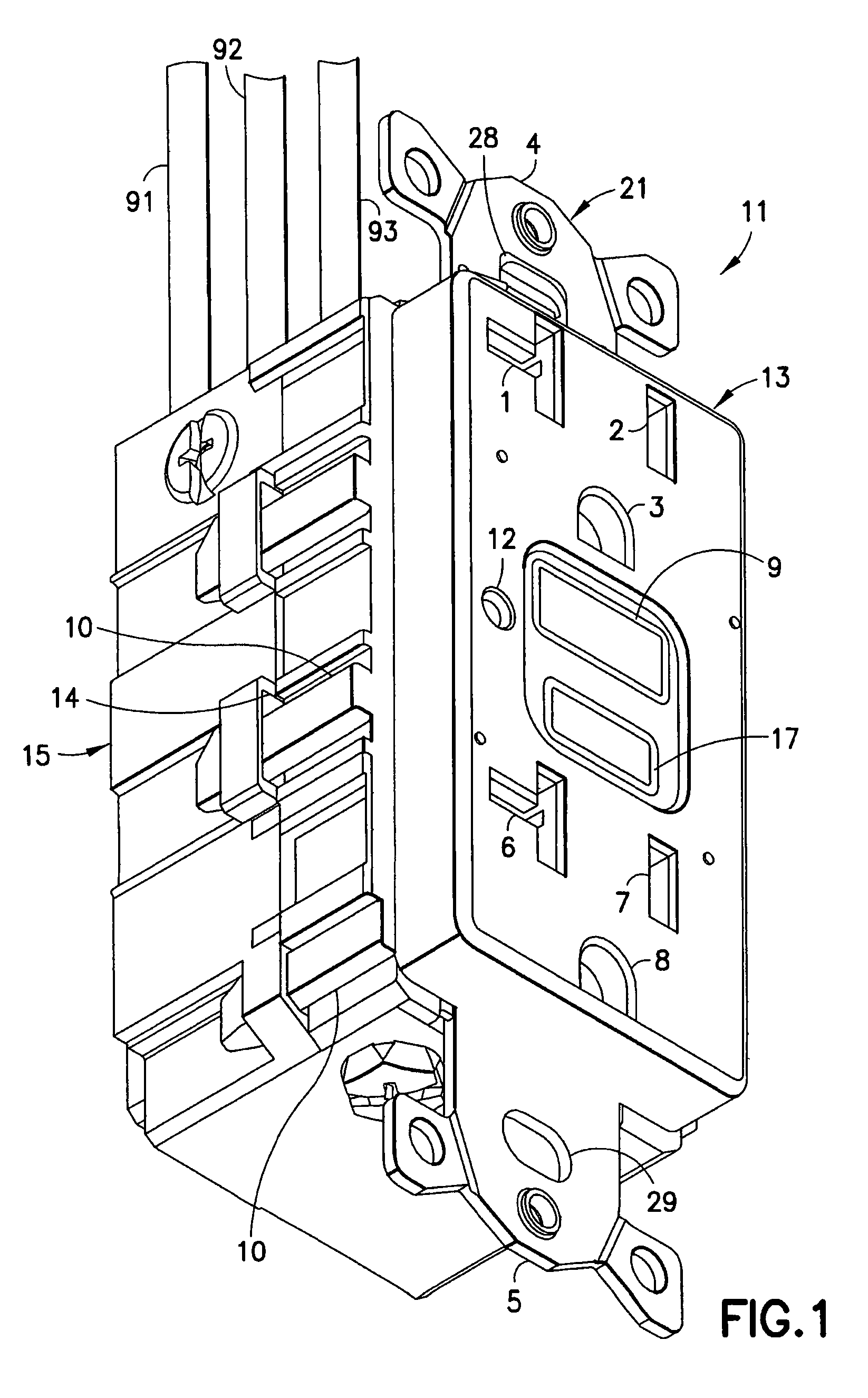
[0027]An electrical device assembly in accordance with an exemplary embodiment of the present invention includes an electrical device or GFCI receptacle 11 and a plug connector 31 adapted to be received thereby, as shown in FIGS. 1-10. The electrical device 11 includes a housing having a rear surface 19 and an aperture 18 in the rear surface. A ground strap 21 is connected to the housing and is adapted to secure the electrical device 11 to an electrical box. A plurality of contact blades 22-24 are disposed in the electrical device 11 and are accessible through the aperture 18 (FIG. 4). One of the contact blades is a ground contact blade 23. A grounding member 41 extends between the ground contact blade 23 and the ground strap 21 (FIG. 7). The plug connector 31 includes a plurality of contact members 61, 62 and 63 adapted to engage the plurality of contact blades 22-24 in the electrical device 11 (FIG. 6). A plurality of wires extend outwardly from the plurality of contact members 22...


PUM


Abstract

An electrical device assembly includes an electrical device and a plug connector adapted to be received thereby. The electrical device includes a housing having a rear surface and an aperture in the rear surface. A ground strap is connected to the housing and is adapted to secure the electrical device to an electrical box. A plurality of contact blades are disposed in the electrical device and are accessible through the aperture. One of the contact blades is a ground contact blade. A conductive member extends between the ground contact blade and the ground strap. The plug connector includes a plurality of contact members adapted to engage the plurality of contact blades in the electrical device. A plurality of wires extend outwardly from the plurality of contact members such that the plurality of wires are substantially parallel to the rear surface of the electrical device when the plug connector is connected to the electrical device, thereby providing an electrical device assembly having a low profile.

Description

FIELD OF THE INVENTION[0001]The present invention relates to an electrical device assembly having a low profile. More particularly, the present invention relates to a GFCI device having a rear aperture for receiving a plug connector in which the wires terminated by the plug connector are substantially parallel to a longitudinal axis of contact members disposed within the plug connector. Still more particularly, the present invention relates to a GFCI device having a grounding member connecting a plug connector to a ground strap of the GFCI device.BACKGROUND OF THE INVENTION[0002]GFCI devices are designed to trip in response to the detection of a ground fault condition at an alternating current (AC) load. Generally, the ground fault condition results when a person or object comes into contact with the line side of the AC load and an earth ground at the same time, a situation which can result in serious injury.[0003]GFCI devices interrupt a circuit path, typically at an AC receptacle,...

Claims


Application Information

Patent Timeline
Patent Type & Authority Patents(United States)
IPC IPC(8): H01R13/46
CPCH01H83/02H01R13/7135
Inventor PADRO, KENNY
Owner HUBBELL INC
Why Eureka
Eureka Blog
Learn More