
Coupling lock for a trailer coupling

a technology of coupling lock and trailer, which is applied in the direction of towing device, vehicle components, transportation and packaging, etc., can solve the problems of inability to coupling and decoupling the trailer vehicle, no system sufficiently well developed for mass production, and much more difficult problems

Inactive Publication Date: 2013-01-01
ZF FRIEDRICHSHAFEN AG
View PDF13 Cites 51 Cited by
  • Summary
  • Abstract
  • Description
  • Claims
  • Application Information

AI Technical Summary

Benefits of technology

The present invention aims to develop a coupling lock that can be easily coupled and decoupled. As a further development, a magnetically adhering body is used that is placed between the coupling element and the adhering magnet. This makes it possible to strengthen the magnetic attraction between them. The pot, in which the adhering magnet is placed, is designed with a rim that delimits the opening, and a gap is left between the adhering magnet and the pot's wall. This gap protects the adhering magnet from mechanical loads and allows it to be held in a fixed manner. This invention simplifies the process of coupling and decoupling.

Problems solved by technology

Until now no system that is sufficiently well developed for mass production has been available for sensing the pivot angle between the coupling element and the coupling lock, which is also referred to as the combination angle.
The disadvantage of this is that owing to measuring equipment of this type the coupling and decoupling of the trailer vehicle is no longer possible, or much more difficult, since the measuring equipment comprises part-systems on both the tractor vehicle and the trailer, which are sometimes even connected together mechanically.
Moreover, such measuring equipment is as a rule not suitable for operation under adverse environmental conditions (humidity, temperatures).

Method used


Image

  • Coupling lock for a trailer coupling
  • Coupling lock for a trailer coupling
  • Coupling lock for a trailer coupling

Examples


Embodiment Construction

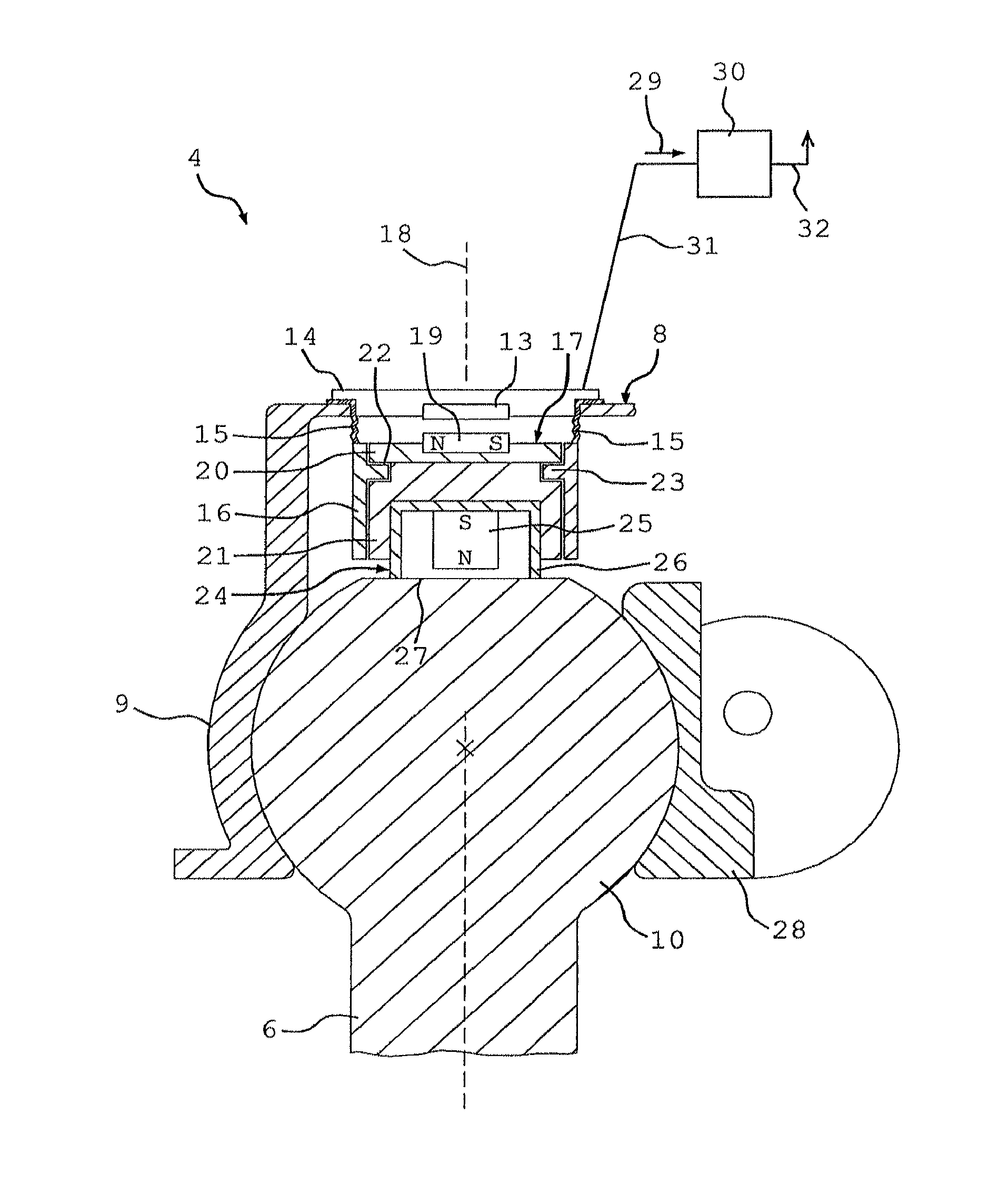
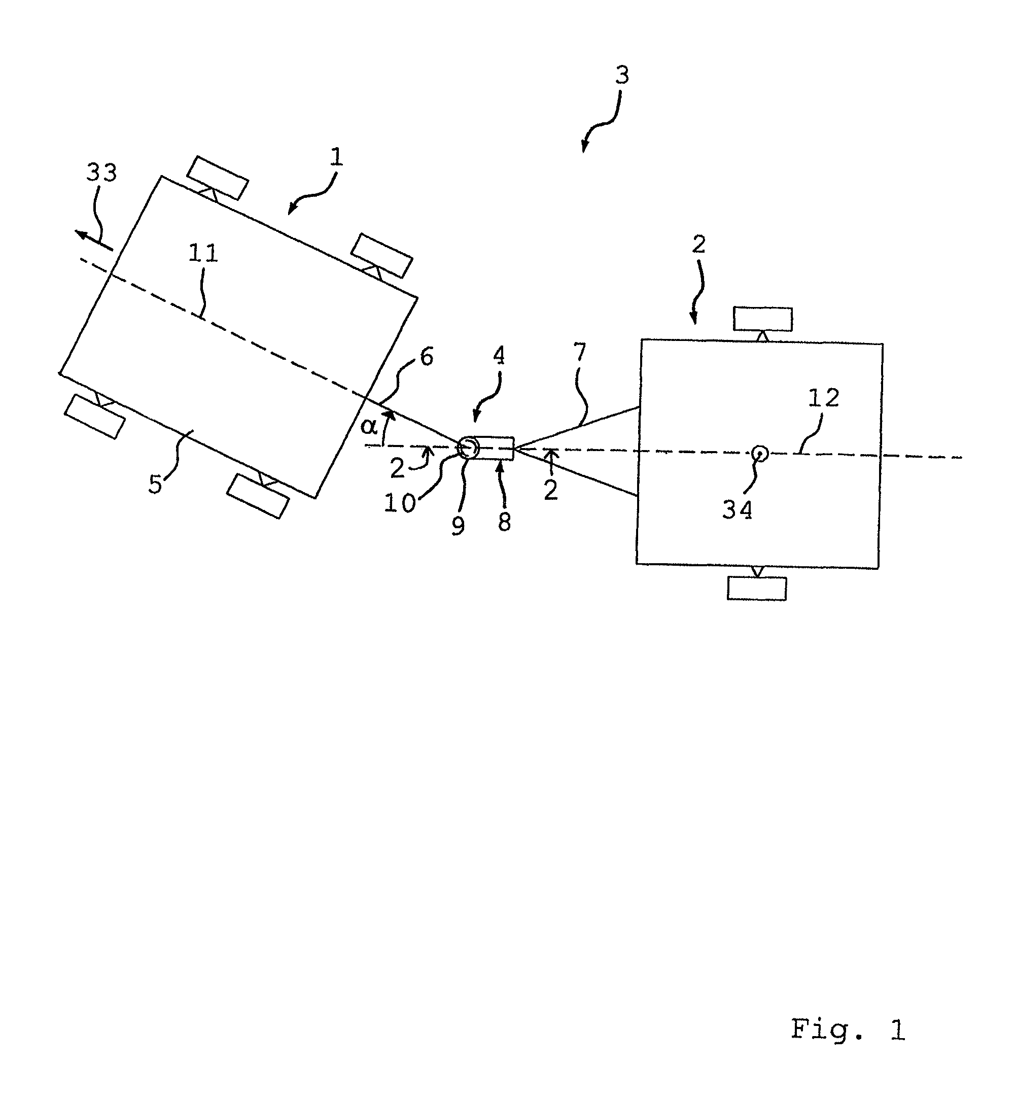
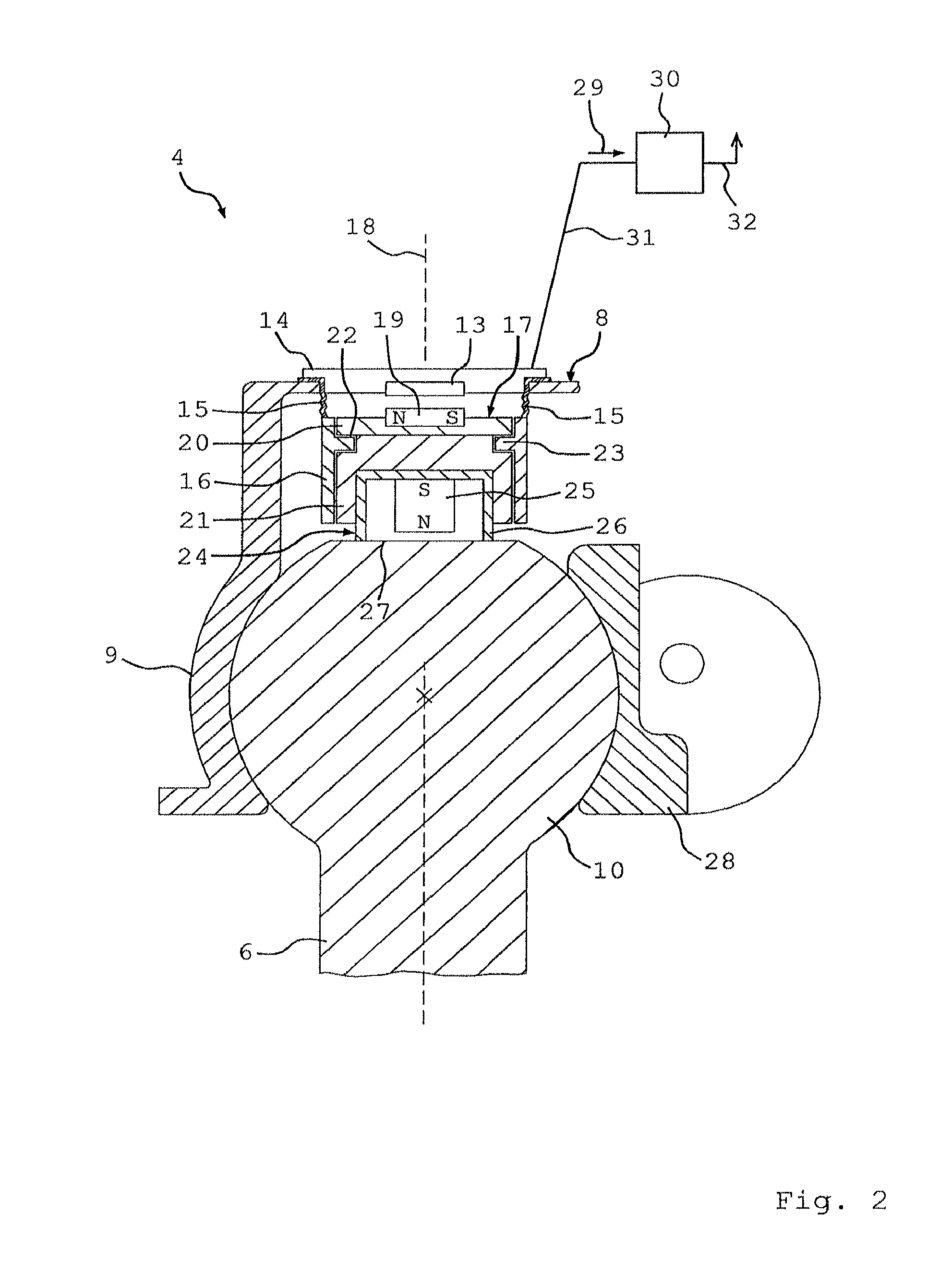
[0034]FIG. 1 shows a top view of a combination 3 comprising a tractor vehicle 1 and a trailer vehicle 2, in which the tractor vehicle 1 is articulated to the trailer vehicle 2 by means of a trailer coupling 4. The normal forward driving direction of the tractor vehicle 1 and / or the combination 3 is indicated by the arrow 33. The trailer coupling 4 comprises a coupling element 6 connected solidly to the chassis or vehicle body 5 of the tractor vehicle 1 and a coupling lock 8 fixed onto a towbar 7 of the trailer vehicle 2.

[0035]The coupling lock 8 comprises a ball socket 9 into which a schematically represented ball head 10 of the coupling element 6 is fitted, such that the ball head 10 forms an end of the coupling element 6 at the rear thereof in relation to the driving direction 33. Furthermore, the coupling lock 8 forms a front end of the towbar 7 in the driving direction 33.

[0036]The angle a between the longitudinal axis 11 of the tractor vehicle 1 and the longitudinal axis 12 of ...


PUM


Abstract

A coupling lock for a trailer coupling. The coupling lock comprises a receptacle (9) in which a coupling element (6) is inserted, an angle measuring device (13, 19) is connected to the receptacle (9), and the angle measuring device (13, 19) is provided for detecting rotation of the receptacle (9), about a rotational axis (18), relative to the coupling element (6). A magnetically adhering body (24) is elastically connected to the receptacle (9) and magnetically connectable to the coupling element (6) for actuating the angle measuring device (13, 19).

Description

[0001]This application is a national stage completion of PCT / DE2010 / 050038 filed Jun. 17, 2010, which claims priority from German Application Serial No. 10 2009 027 036.1 filed Jun. 19, 2009.FIELD OF THE INVENTION[0002]The invention concerns a coupling lock for a trailer coupling, with a receptacle in which a coupling element is or can be inserted and an angle measuring device connected with the receptacle, by means of which rotation of the receptacle relative to the coupling element about a rotational axis is or can be detected.BACKGROUND OF THE INVENTION[0003]A trailer coupling for a tractor / trailer combination as a rule comprises a coupling lock with a receptacle in which a coupling element can be inserted. The coupling lock and the coupling element form an articulated joint so that the tractor vehicle can pivot relative to the trailer vehicle, for example when the combination has to drive round a curve. In this case the coupling lock is fixed on one vehicle of the combination an...

Claims


Application Information

Patent Timeline
Patent Type & Authority Patents(United States)
IPC IPC(8): B60D1/06
CPCB60D1/065B60D1/58B60D1/305B60D1/30
Inventor ALBERS, INGOELBERS, CHRISTOPHSPRATTE, JOACHIMMATZOLD, KATHARINA
Owner ZF FRIEDRICHSHAFEN AG
Learn More