
Surgical tool and method of operation

a surgical tool and a technology for assisting with medical procedures, applied in the field of surgical tools and methods of operation, to achieve the effect of reducing the chance of patient being inadvertently injured and lowering the risk of infection

Inactive Publication Date: 2012-12-18
OKAY INDS
View PDF17 Cites 74 Cited by
  • Summary
  • Abstract
  • Description
  • Claims
  • Application Information

AI Technical Summary

Benefits of technology

"The invention provides a surgical tool with a pivot and a slot for a clevis, which can be moved by a cable and pulley system. The tool can also have a handle and a mechanism for rotating the end effector. The method of operating the tool involves moving the cable in one direction, which causes the clevis to move in a different direction. This movement causes the end effector to rotate in different directions. The technical effect of this invention is to provide a surgical tool with improved precision and control for the surgeon during surgery."

Problems solved by technology

The smaller the instrument, the smaller the incision and the lower the risk of infection.
This reduces the chances of the patient being inadvertently injured during the withdrawal or insertion of the instruments.

Method used


Image

  • Surgical tool and method of operation
  • Surgical tool and method of operation
  • Surgical tool and method of operation

Examples


first embodiment

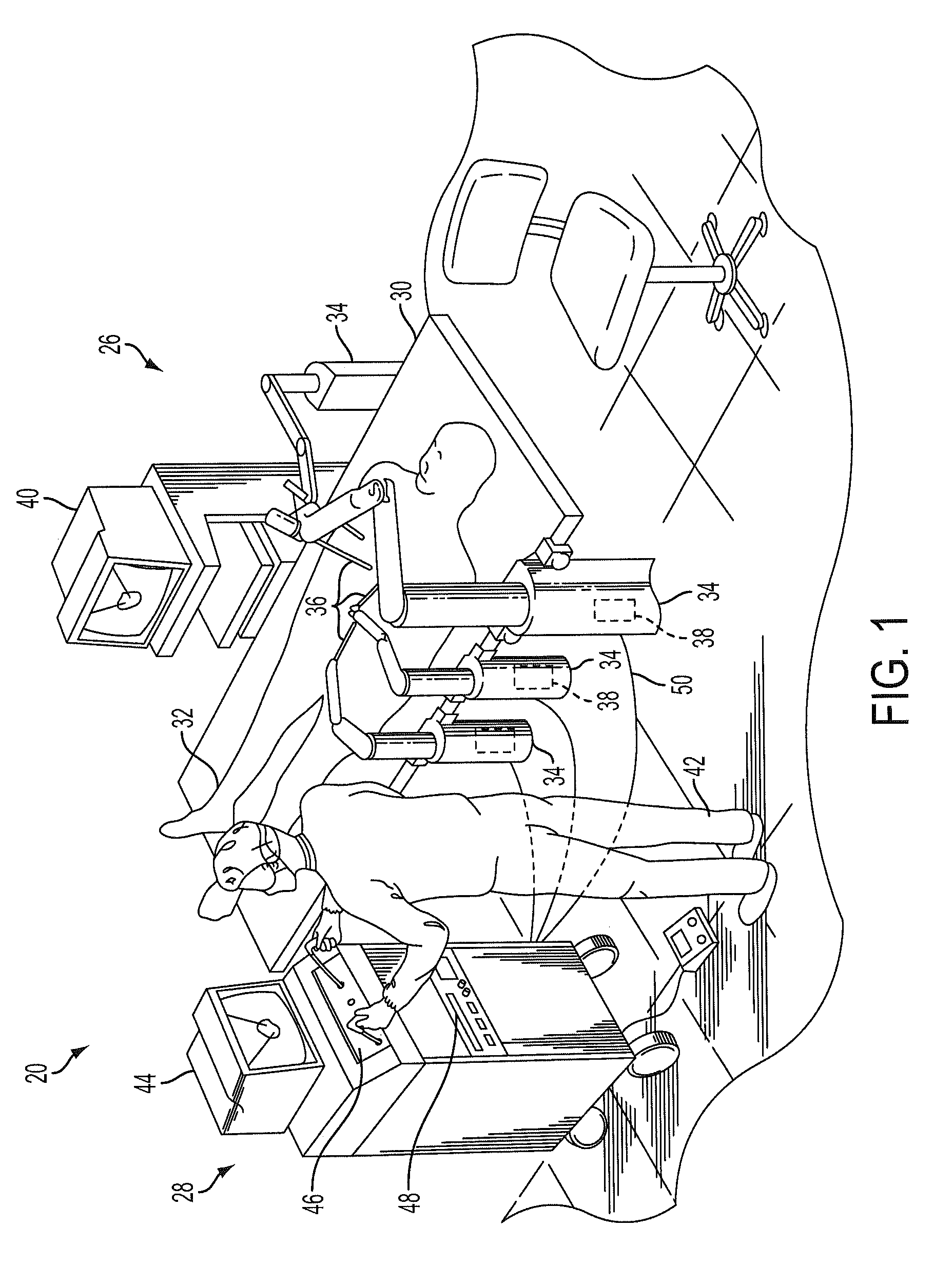
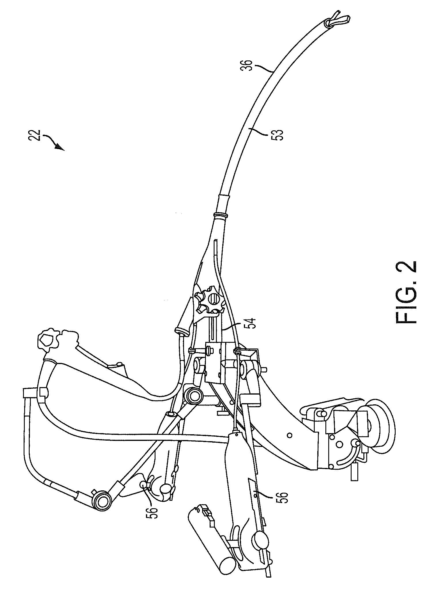
[0034]FIGS. 1-3 illustrate exemplary embodiments of surgical systems 20, 22, 24 that assist surgeons in performing minimally invasive medical procedures. The first embodiment is a robotic type surgical system 20. The robotic surgical system 20 includes an operating table unit 26 and a remote control unit 28. It should be appreciated that while the remote control unit 28 is illustrated as being disposed adjacent the operating table unit 26, this is merely for illustration purposes and the control units 26, 28 may also be located in geographically distant areas. The operating table unit 26 includes a platform 30 upon which the patient 32 rests during the procedure. Attached to the platform 30 is one or more surgical apparatus 34 that includes a plurality of surgical tools 36. The surgical apparatus 34 also includes an actuator or motor 38 that is coupled to move and articulate the surgical tools 36. The operating table unit 26 may also include one or more monitors 40 that may be used ...

third embodiment

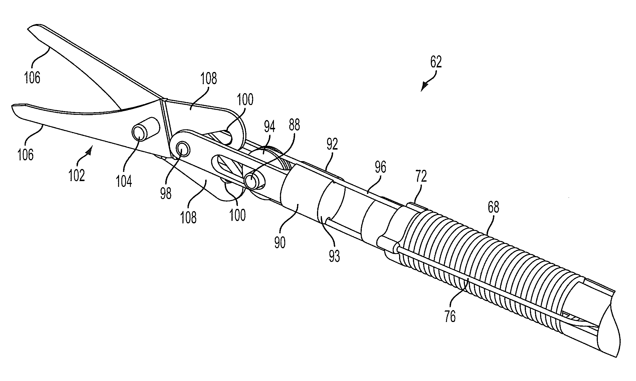
[0037]The third embodiment is a manual hand held surgical system 24 illustrated in FIG. 3. This embodiment includes a surgical tool 36 that is directly coupled to a handle 58 having an actuation knob 60. In this embodiment, the surgeon holds the surgical system 24 without the assistance of any support frames or devices. As will be discussed in more detail below, the surgical tool portion 36 includes an end effector 62 that the surgeon uses to perform procedures within the patient. As used herein, the end effector 62 may include, but is not limited to scissors, forceps, graspers, punches and fan style retractors for example. During the medical procedure, the surgeon inserts the end effector 62 through an incision and directly manipulates the orientation, position and angle of the end effector62. The surgeon uses the actuation knob 60 to control the position and state of the end effector 62. As will be discussed below, in some embodiments a mechanical arrangement is provided to rotate...


PUM


Abstract

A surgical tool and method of operation are provided. The surgical tool includes an end effector, such as a surgical scissor. The end effector is coupled to an actuating mechanism having a clevis and a pulley. A cable engages the pulley and is attached to one side of the clevis. When one portion of the cable is pulled, the clevis is moved in a first direction causing the end effector to open. When a second portion of the cable is pulled, the clevis moves in the opposite direction and the end effector is closed. The system also includes a mechanism for changing the orientation of the end effector. Another embodiment includes a mechanism for actuating the cable and the end effector.

Description

BACKGROUND OF THE INVENTION[0001]The present invention relates generally to a device for assisting with a medical procedure and, more specifically, to a device that may be directly actuated by a surgeon, or used in conjunction with a robotic surgery system.[0002]Minimally invasive surgical procedures have gained increased acceptance within the medical community. These procedures, sometimes referred to as laparoscopic, endoscopic, arthroscopic or keyhole surgery for example, use several small incisions to provide the surgeon access to the areas of the patient requiring attention. These incisions are small, typically on the order of 0.5 cm-1.5 cm. The surgeon uses a camera to view the surgical area and control tools or implements during the operation. These implements include tools such as cameras, forceps, cutters or dissectors for example. A device known as a trocar is often used in the incision during the procedure to allow the insertion and removal of the implements during the sur...

Claims


Application Information

Patent Timeline
Patent Type & Authority Patents(United States)
IPC IPC(8): A61B17/32
CPCA61B17/29A61B19/2203A61B2017/00314A61B2017/00327A61B2017/2923A61B2017/2927A61B2017/2936A61B2019/2215A61B2019/2238A61B2019/2242A61B2034/302A61B34/71A61B34/30A61B2034/306
Inventor PEDROS, ROBERTOREED, SCOTTWILSON, PETE
Owner OKAY INDS
Learn More