
Utility cutter with a non-tool blade changer

a blade changer and utility cutter technology, applied in the direction of manufacturing tools, portable power-driven tools, metal working apparatuses, etc., can solve the problems of occupying additional space, requiring and the prior art blade changing mechanism is too cumbersome and requires too many parts or movements

Active Publication Date: 2012-12-11
RONAN JOHN S
View PDF59 Cites 16 Cited by
  • Summary
  • Abstract
  • Description
  • Claims
  • Application Information

AI Technical Summary

Benefits of technology

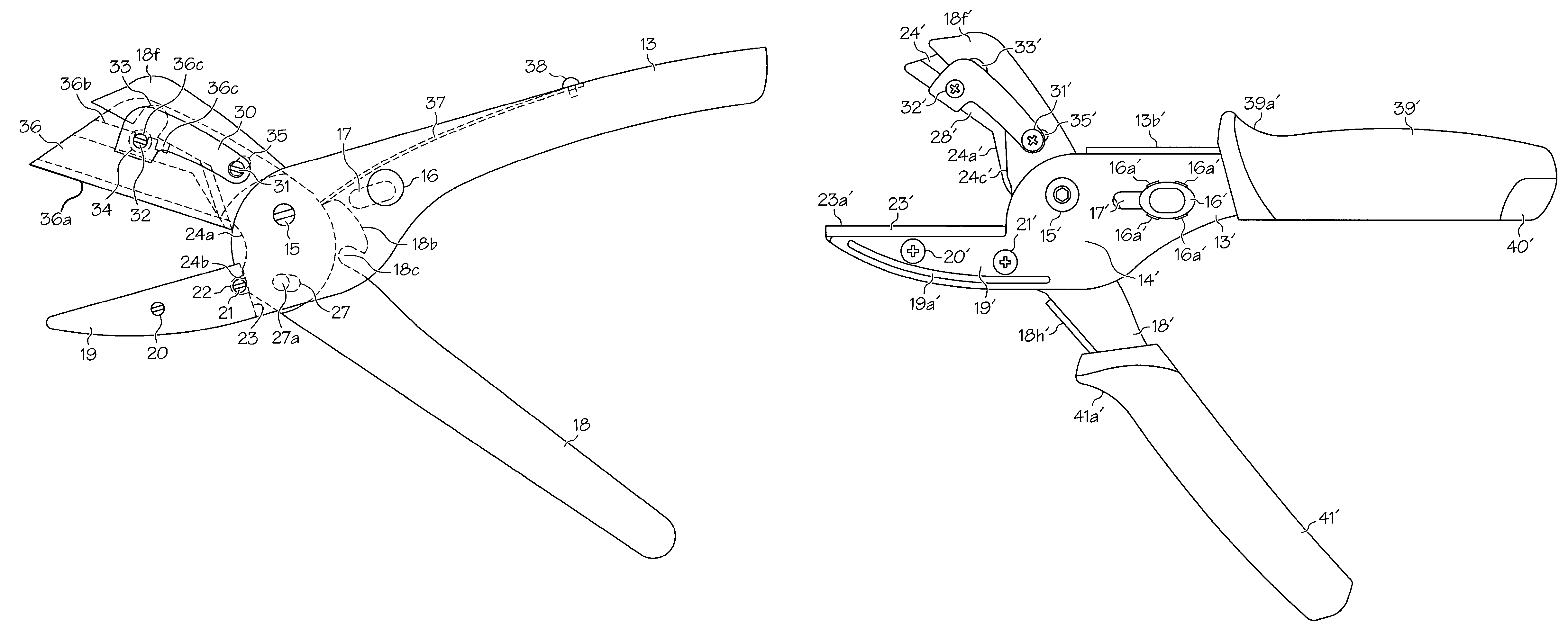
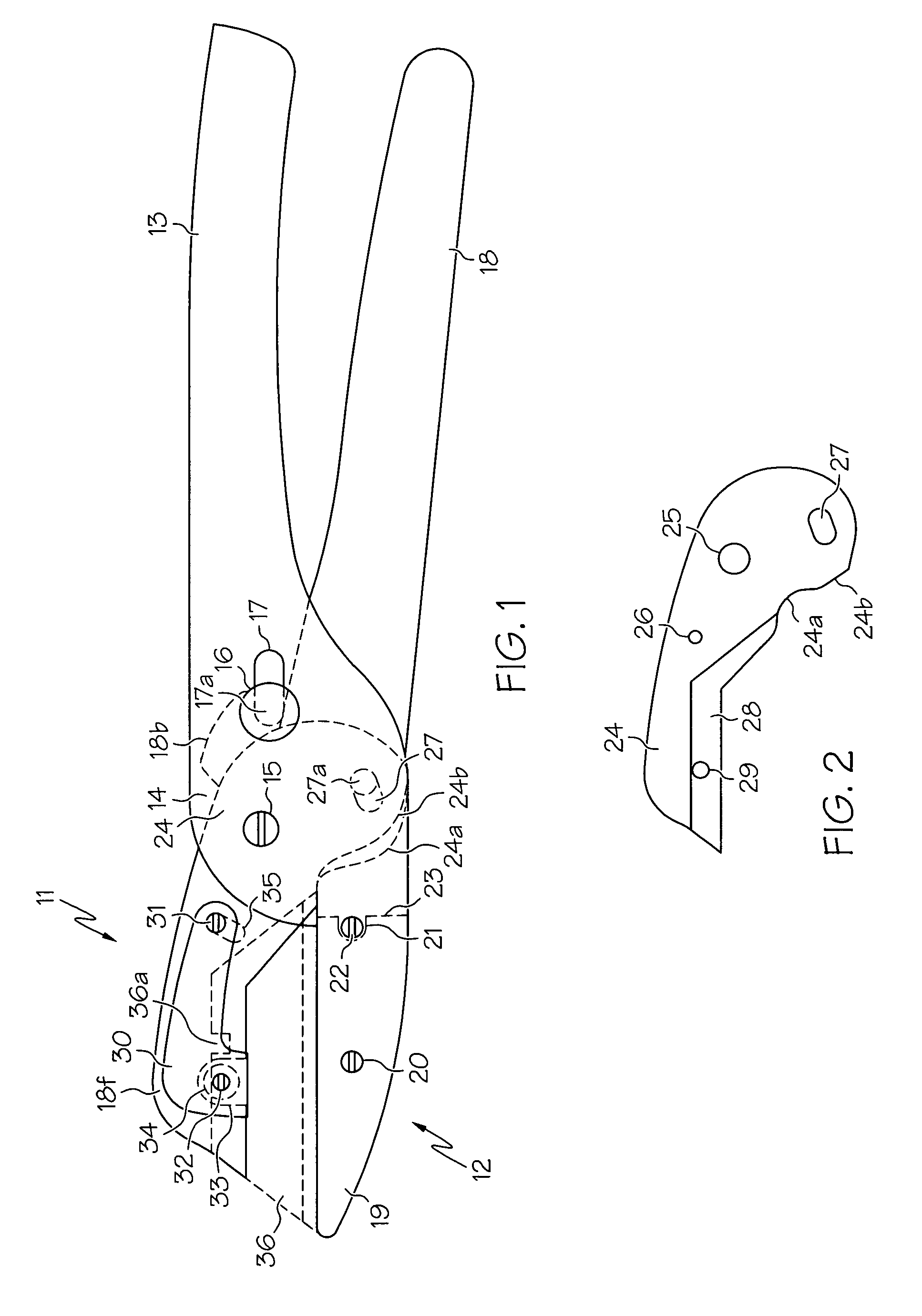
[0029]The present invention is a blade and anvil type cutting tool or device that uses standard type razor blades with an integral non-tool blade changing blade holder assembly and a blade clamp assembly. The standard blades are able to be changed with out tools when the blade holder assembly and the clamp assembly moves away from a latching slot in a sectional portion in one of a pair of handles of the blade and anvil type cutting tool or device into a second fully open blade release position by pivoting the pair of handles beyond a first open position. The first open position allows for material or objects to be placed between a cutting surface of an anvil member and a cutting blade of blade holder and blade clamp assemblies.
[0034]Note that the cooperative and pivotal association between the blade clamp assembly, the blade holder assembly and the handle portions allows the blade holder assembly to move together with the handle portions between open and closed positions. Upon the handle portions being moved from a closed position to a first open position the razor blade element of the blade holder assembly is moved away from the anvil member to permit material or objects to be placed there between to be cut when the handle portions are moved back to a closed position. When the handle portions are moved further outward of the first open position, a second open release position is achieved. This open release position allows the blade holder assembly to be pivotally released from the blade clamp assembly to allow easy removal of the razor blade without the use of tools.
[0036]In addition, the second preferred embodiment of the present invention, the first and second handle gripping ends includes a handle gripping member thereon. The first handle portion between the rear gripping end and the intermediate securing section defines an inclined abutment surface. The first handle gripping handle member has an opening therein for receiving a sliding razor blade storage tray. Note that the inclined abutment surface extends downwardly a desired distance from the first handle portion rear gripping end to form a desired space of a certain height within the opening of the handle gripping member when it is installed on the rear gripping end of the first handle portion. This desired space allows the sliding tray to clear the under portion of the rear gripping end of the first handle portion. Also, when additional razor blades are stored within the tray, the tray will be able to move freely within the opening of the handle gripping member without any complications. Furthermore, the sliding tray forward end will abut the inclined abutment surface when the tray is fully inserted within the handle gripping member of the first handle portion. Also, the sliding tray has at least a pair of spring-loaded retention members on opposite sides thereof to latch the tray within the handle gripping member against at least a pair of retention surfaces on opposite sides therein. The sliding tray rear end has a gripping end surface for allowing a user to easily grip and move the sliding tray in and out of the handle gripping member.
[0037]Finally, this blade and anvil type cutting tool or device can be converted easily into a multi-function tool such as a utility knife and an anvil cutting tool by merely selectively adjusting the blade relative to the anvil in one of a plurality of selected adjustment apertures or slots of a stand razor blade.

Problems solved by technology

One of the shortcomings being that the prior art blade changing mechanisms are too cumbersome and requires too many parts or movements.
Many of the blade changing tools are bulky and time consuming in replacing razor blades of the prior art utility cutting devices.
Some of these tools have to be incorporated or attached to the prior art utility cutting devices or tools, which take up additional space.
Even for the prior art cutting devices or tools that do not utilize tools, they have to be shaken vigorously so that the razor blades are loosen which can cause the razor blade to fly out, which can cause serious injury to someone or utilizes more force to remove them.
Such space or compartment design can increase cost and size of the utility cutting devices or tools.
Also, this design can take away from the aesthetics of the utility cutting devices or tools.
Although these prior art cutting devices or tools might be creative, and well-thought-out inventions, that function well for their intended purposes at the time of their creation, but some, if not all are cumbersome and not timely in replacing cutting razor blades from a blade holder and blade clamp assembly, utilizes too much space in the body of the cutting devices or tools to define razor blade storage compartments and requires unnecessary tools, screws or force to remove the razor blades from the blade holder and blade clamp assembly.
Also, none of the prior art patents teach the unique sliding spring-biased detent storage tray for replacement razor blades solely within a handle grip cover and not in the body of a cutting device or tool.

Method used


Image

  • Utility cutter with a non-tool blade changer
  • Utility cutter with a non-tool blade changer
  • Utility cutter with a non-tool blade changer

Examples


Embodiment Construction

[0065]Reference will now be made in detail to the preferred embodiments of the invention, examples of which are illustrated in the accompanying drawings. While the invention will be described in conjunction with the accompanying drawings, it will be understood that they are not intended to limit the invention to the accompanying drawings. On the contrary, the present invention is intended to cover alternatives, modifications and equivalents, which may be included within the spirit and scope of the invention as defined by the appended claims.

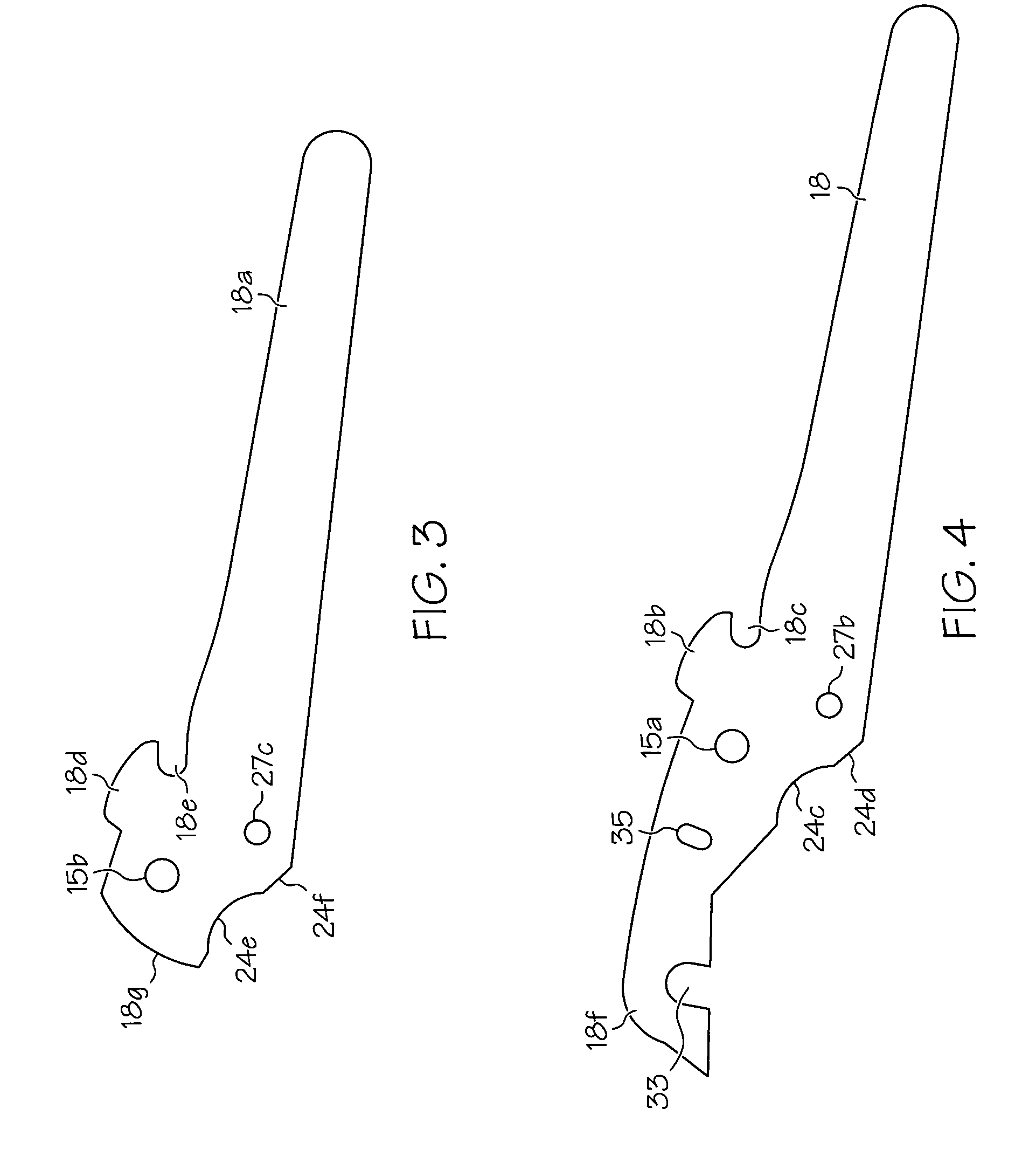
[0066]FIG. 1 of the first preferred embodiment of the present invention shows a utility cutter device with blade holder and blade clamp assemblies 11 and an anvil section 12. The utility cutter includes handle portions 13 and 18 with spaced apart complimentary handle portions. The handle portions 13 and 18 have a spacer member (not shown) there between for securing the handle complimentary portions together with a plurality of fastening means (no...


PUM


Abstract

A multi-function blade-and-anvil type cutting tool that uses standard type razor blades includes a blade-and-anvil section connected to a first handle portion and a non-tool blade holder and a blade clamp assembly connected to a second handle portion. The standard blades are able to be changed with out tools when the first and second handle portions are moved from a first open position to a second open position to allow the blade holder and the clamp assembly to pivot with one another causing a screw and O-ring latch to move away from a latching slot in the second handle portion. This movement positions the razor blade between the screw and O-ring latch and a blade clamp guide element for easy removal. Each handle portion having a gripping cover disposed thereon. One of the handle portions has a sliding storage tray disposed therein for storing replacement razor blades.

Description

CROSS REFERENCE TO RELATED APPLICATION(S)[0001]This application is based upon and claims the priority of U.S. Provisional Patent Application Ser. No. 61 / 202,358, filed on Feb. 23, 2009.BACKGROUND OF THE INVENTION[0002]1. Field of the Invention[0003]The present invention relates generally to conventional fixed blade knives / shears and other cutter type devices. More particularly, the present invention relates to blade and anvil type cutting devices or tools that can be easily converted to conventional fixed blade knives / shears type cutting devices. This invention more specifically relates to a utility cutting device with a blade holder and a movable or pivoted blade clamp changing mechanism for easily removing razor cutting blades from the utility cutting device without the use of any tools. Further, the present invention relates to a razor blade storage compartment within a handle gripping cover positioned on at least one of the pair of pivoted handle of the utility cutting device.[0...

Claims


Application Information

Patent Timeline
Patent Type & Authority Patents(United States)
IPC IPC(8): B26B17/00
CPCB26B17/00
Inventor RONAN, JOHN S.
Owner RONAN JOHN S
Learn More