
Method and arrangement for an improved buffer solution within a communication network switch

a communication network switch and buffer solution technology, applied in the field of switches, can solve the problems of imposing additional delay of packets already in the packet ring, unable to achieve total asynchronous ip (aip), and potentially expensive principle, and achieves the effects of optimizing buffer performance, minimizing packet loss ratio (plr), and packet reordering

Active Publication Date: 2012-11-20
TRANSPACKET
View PDF14 Cites 0 Cited by
  • Summary
  • Abstract
  • Description
  • Claims
  • Application Information

AI Technical Summary

Benefits of technology

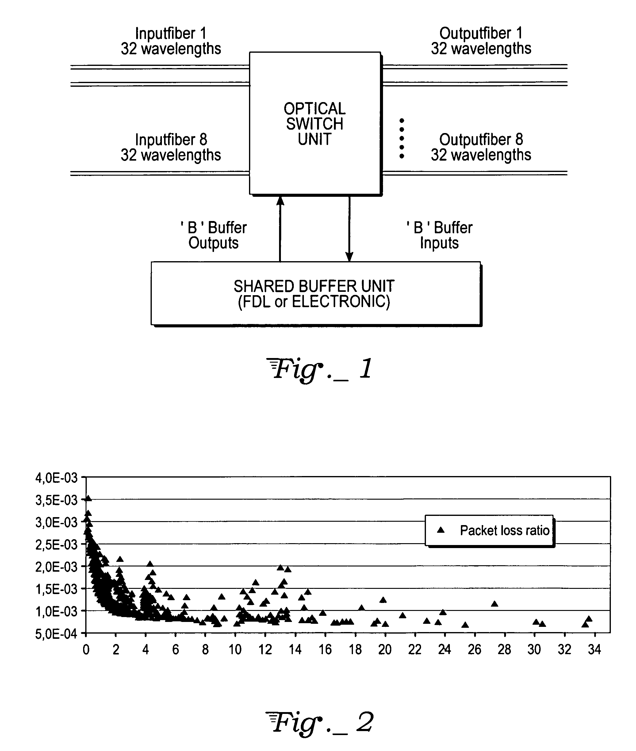
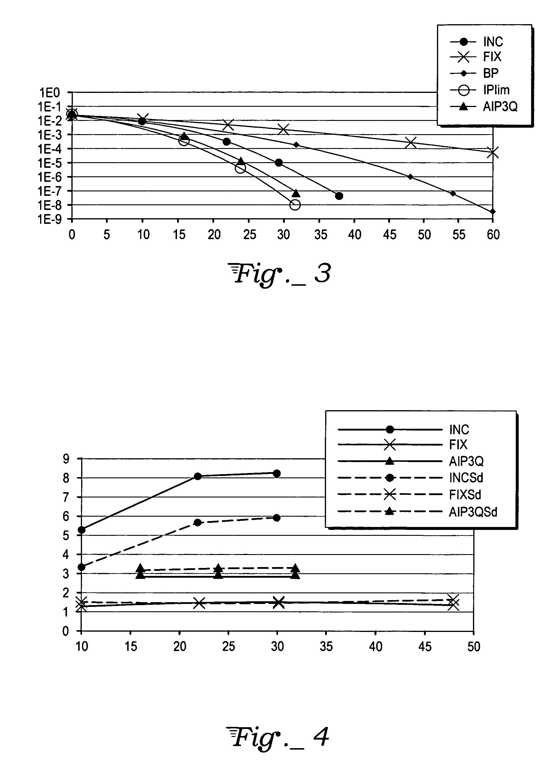
[0014]Furthermore according to the present invention we distribute buffered packets into a number of Queues in accordance with the packet length distribution. We optimize for systems using a wavelength dimension for contention resolution with the goal of optimizing the buffer performance with respect to minimizing Packet Loss Ratio (PLR) and packet reordering.

Problems solved by technology

Two main issues of interest in OPS are however optical synchronization and buffering.
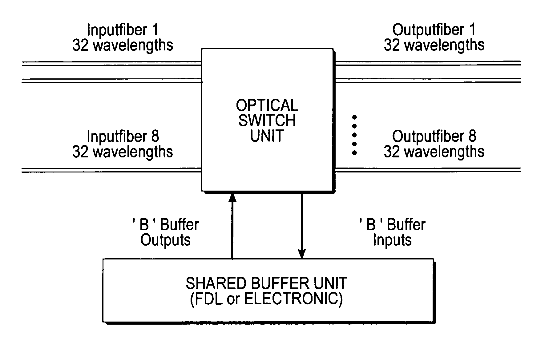
However, if the buffer has fewer input interfaces than the total number of switch inputs, only a fraction of the packets passing through the switch will be buffered and hence, delayed [1,4].
A new packet can arrive at the input at any random moment after a packet was scheduled from the buffer, hence making total Asynchronous IP (AIP) impossible when the number of buffer ports is limited.
Further, in asynchronous optical Metro packet rings, the same problem as above arises.
However, this calls for extra components, both detectors and FDLs, making the principle potentially expensive.
This will impose additional delay of the packets already in the packet ring.

Method used


Image

  • Method and arrangement for an improved buffer solution within a communication network switch
  • Method and arrangement for an improved buffer solution within a communication network switch
  • Method and arrangement for an improved buffer solution within a communication network switch

Examples


Embodiment Construction

[0020]In the following is given a detailed description of a queue arrangement system of general usage; however for ease of understanding it is described with references to telecommunication and data communication systems. The disclosed arrangement and method is characterized in that it is very flexible in that it employs a feedback buffer, wherein the feedback buffer can be of any kind provided it can be accessed at an arbitrary point of time. Further to accomplish the advantages of the present invention the queue system will be of a type where there is a number of queues and the queues are prioritizing queues where certain parameters are used to decide the amount of queues and / or the dimensioning of the queues. Within telecommunication and / or data communication a natural choice for the criterion parameter is the length of the packets of data and / or the length of the data in other formats such as databursts, data streams or any other dataflow that can be split into packets.

[0021]“Sw...


PUM


Abstract

In asynchronous optical packet switches, scheduling packets from a buffer randomly will cause less efficient utilization of the buffer. Additionally, reordering of packets may cause problems for service quality demanding applications. According to the present invention a new electronic buffer scheduling algorithm is proposed and a switch utilizing this algorithm is disclosed. The algorithm is designed for utilizing the buffer resources efficiently, still avoiding serious packet reordering.

Description

BACKGROUND OF THE INVENTION[0001]1. Field of the Invention[0002]The present invention relates to a switch and a method for organizing dataflow through a switch within packet switched or bursts switched networks. More particularly it relates to a switch within a telecommunication or data communication network, where the switch includes one or more outputs and a buffer unit, further it relates to a method for organizing dataflows in a telecommunication or data communication network including at least one switch where said switch is associated with at least one buffer.[0003]2. Background Art[0004]Despite the economic recession, network traffic continues to grow. Optical Packet Switching (OPS) is a promising candidate for a future cost effective network, supporting both high throughput and utilization. Two main issues of interest in OPS are however optical synchronization and buffering. Recently, a number of works have focused on using asynchronous packet switching, thereby avoiding the...

Claims


Application Information

Patent Timeline
Patent Type & Authority Patents(United States)
IPC IPC(8): H04L12/28H04J14/00H04L12/56H04Q11/00
CPCH04Q11/0005H04L49/103H04L49/254H04Q2011/002
Inventor BJORNSTAD, STEINAR
Owner TRANSPACKET
Learn More