
Smart circuit breaker with integrated energy management interface

a smart circuit breaker and energy management technology, applied in the field of circuits, can solve the problems of limiting the ability of the energy consumer to manage the electrical load, affecting the performance of the circuit breaker, and generally exceeding the capability of the average energy user, and achieves the effect of convenient installation

Active Publication Date: 2012-11-13
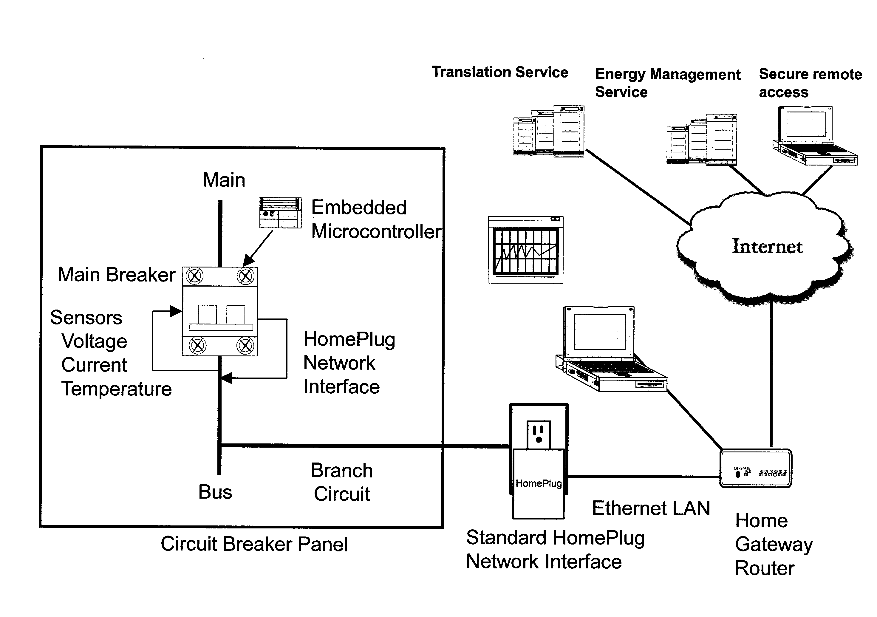
SOUTHERN COMPANY SERVICES
View PDF9 Cites 44 Cited by
  • Summary
  • Abstract
  • Description
  • Claims
  • Application Information

AI Technical Summary

Benefits of technology

[0003]The embodiments of the disclosure provide a drop-in replacement for circuit breakers that contains a microprocessor with sensors, a data acquisition and computational element, a communications element, and a presentation element, all in one easy to install molded case. The drop-in replacement can be for the main circuit breaker or any combination of branch circuit breakers. The National Electrical Code's provision for “Classified Circuit Breakers,” commonly referred to as interchangeable breakers, provides for other manufactures participation in the electrical panel board space.
[0004]In exemplary embodiments, voltage, current, and temperature sensors are added to the circuit breaker assembly along with four logical software elements. The software elements include: (1) data acquisition and computational element; (2) formatting and presentation software; (3) central control element, operating system, and application software; and (4) communication element and driver software. The data acquisition and computational element can store and format the sensor data. The presentation element, at a minimum, can contain both a Web server for easy configuration and reading and a Secure Shell (SSH) protocol daemon for machine to machine communications with other LAN or wide area network (WAN) connected devices. The central control element executes the operating system code and the application code for the (1) watt-hour measuring software; (2) deteriorating neutral conductor detection software; (3) deteriorating ground system detection software; and (4) circuit breaker panel overheating detection software. In addition, the central control element should also include a File Transfer Protocol (FTP) server for firmware updating (i.e., modification) as well as an interface for initial module programming and recovery. The ability to re-flash the software insures compatibility with future energy management services and programs. The communications element allows the data to be transmitted to a web based translation service, to a personal computer, or to an embedded monitor/controller (Energy Plug) via a communications link. This communications element provides a link that could use, but is not limited to, any of the following protocols and technologies: IEEE 802.11a/b/g/n, Bluetooth, HomePlug, Broadband over Power Line (BPL), Power Line Carrier (PLC), Worldwide Interoperability for Microwave Access (WiMAX), ZigBee®, or fiber optic technology in order to meet market demands and customer preferences. A Network Time Protocol (NTP) routine also can be incorp

Problems solved by technology

One of the factors that limit an energy consumer's ability to manage the electrical load is the lack of access to the energy consumer's real-time power consumption.
Although voltage and current sensors can be added to an electrical panel board with discrete sensors, this addition is generally beyond the capability of the average energy user, and generally does not comply with the National Electrical Code (NEC) as adopted by most jurisdictions.
This lack of real-time data impedes the energy consumer's ability to leverage energy management programs that are available on the Web or on local area network (LAN) connected devices.

Method used


Image

  • Smart circuit breaker with integrated energy management interface
  • Smart circuit breaker with integrated energy management interface
  • Smart circuit breaker with integrated energy management interface

Examples


Embodiment Construction

[0042]The following description is provided as an enabling teaching of embodiments of the invention including the best, currently known embodiment. Those skilled in the relevant art will recognize that many changes can be made to the embodiments described, while still obtaining the beneficial results. It will also be apparent that some of the desired benefits of the embodiments described can be obtained by selecting some of the features of the embodiments without utilizing other features. Accordingly, those who work in the art will recognize that many modifications and adaptations to the embodiments described are possible and may even be desirable in certain circumstances. Thus, the following description is provided as illustrative of the principles of the embodiments of the invention and not in limitation thereof, since the scope of the invention is defined by the claims.

[0043]In exemplary embodiments, the Smart Circuit Breaker electronic circuit includes the following functionalit...


PUM


Abstract

A method, system, and apparatus for monitoring electrical safety conditions and managing energy consumption using a microcontroller embedded in a circuit breaker. The microcontroller receives a plurality of inputs detected by a plurality of sensors in the circuit breaker. An amount of energy consumed during a preset interval of time is determined. A temperature of a circuit breaker panel board detected by a temperature sensor is received and compared with a preset temperature alarm threshold value to determine a panel board overheating condition. A condition of the neutral conductor is determined based on a plurality of line voltages and currents received from a plurality of voltage and current sensors by comparing a voltage differential with a preset threshold differential voltage value. A plurality of data values derived from the plurality of sensor inputs and indicative of electrical safety conditions and energy consumption is transmitted via a secure communications link to a data processing system for translation, storage, and presentation to an energy consumer.

Description

TECHNICAL FIELD[0001]Embodiments of the invention relate generally to circuits used in electrical power sensing systems and, more particularly, to smart circuit breakers for monitoring electrical safety conditions and energy management.BACKGROUND OF THE INVENTION[0002]One of the factors that limit an energy consumer's ability to manage the electrical load is the lack of access to the energy consumer's real-time power consumption. Although voltage and current sensors can be added to an electrical panel board with discrete sensors, this addition is generally beyond the capability of the average energy user, and generally does not comply with the National Electrical Code (NEC) as adopted by most jurisdictions. This lack of real-time data impedes the energy consumer's ability to leverage energy management programs that are available on the Web or on local area network (LAN) connected devices. Two such Web-based services for tracking energy consumption are Google PowerMeter and Microsoft...

Claims


Application Information

Patent Timeline
IPC IPC(8): G08B21/00G01R21/00
CPCG01R19/2513
Inventor WILLIAMS, JR., OLIN A.SOLOMON, ARNOLD C.
Owner SOUTHERN COMPANY SERVICES
Learn More