
Methods, cleavers, and packagings for cleaving an optical fiber using an abrasive medium

a technology of abrasive medium and a cleaver, which is applied in the field of cleaving optical fibers, can solve the problems of high poor end face, and insufficient and achieve the effect of reducing the cost of conventional cleaver blades and being sufficiently inexpensiv

Active Publication Date: 2012-11-06
CORNING OPTICAL COMM LLC
View PDF18 Cites 3 Cited by
  • Summary
  • Abstract
  • Description
  • Claims
  • Application Information

AI Technical Summary

Benefits of technology

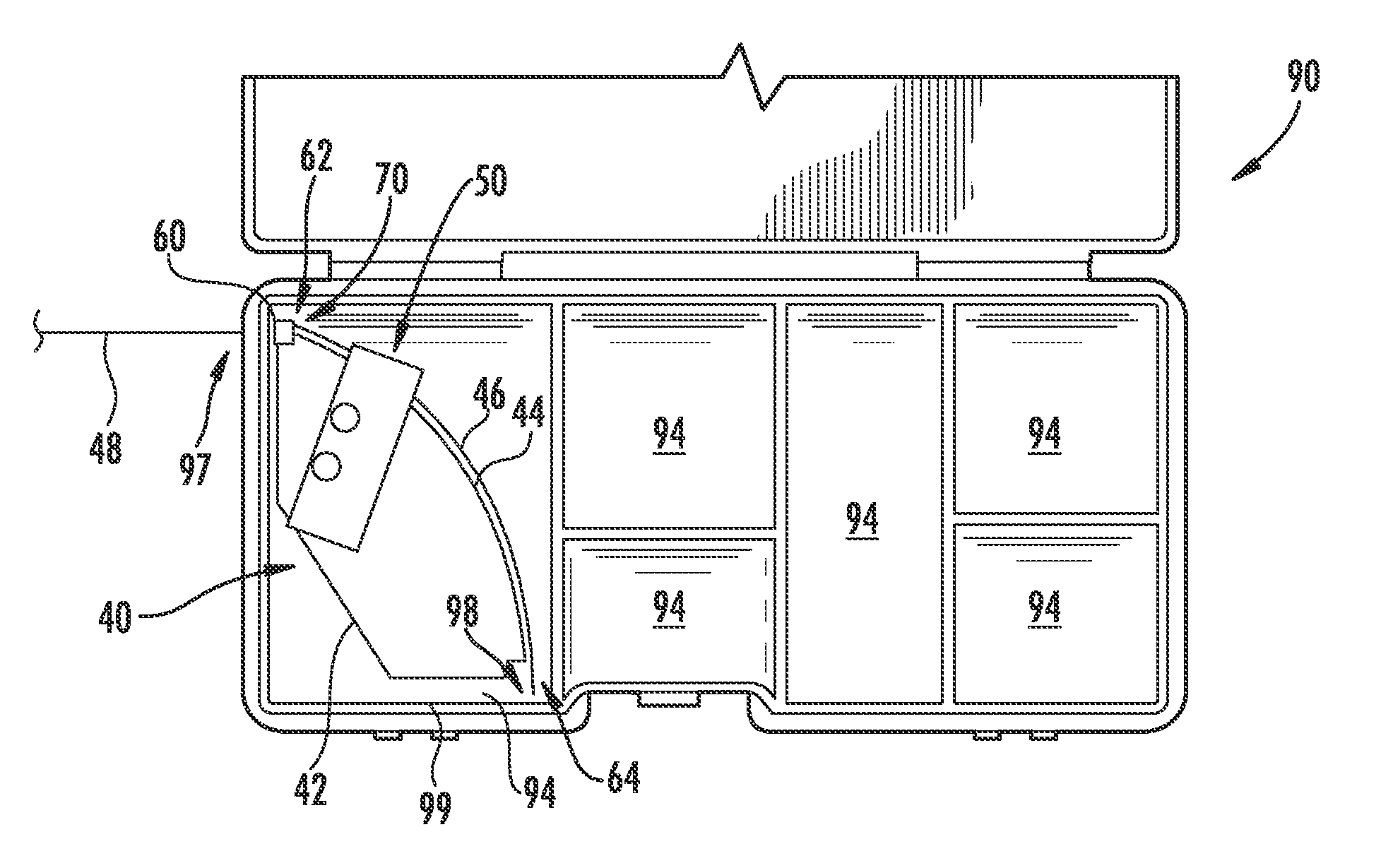
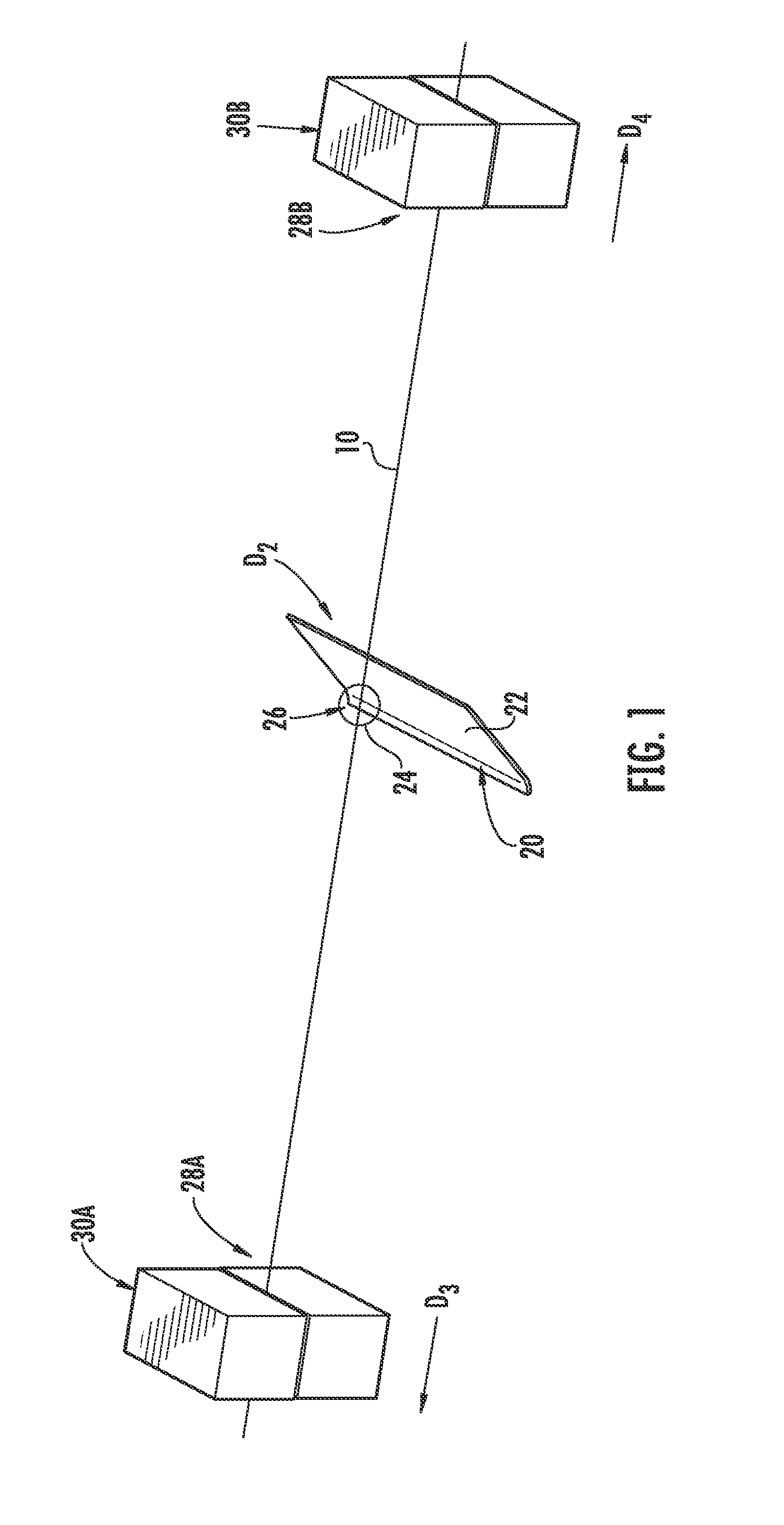
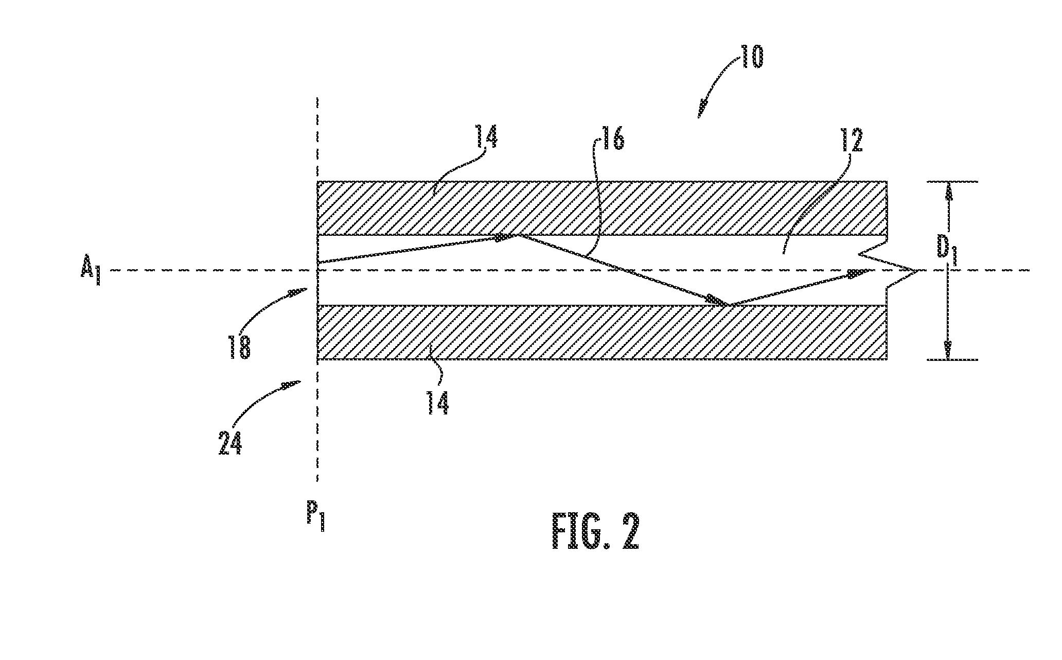
[0007]Embodiments disclosed in the detailed description include methods, cleavers, and packagings for cleaving an optical fiber using an abrasive medium. The abrasive medium may be placed into contact with a portion of an optical fiber to induce a flaw in the portion of the optical fiber. The optical fiber is broken about the induced flaw to create an end face for fiber optic termination preparations. Cleaving the optical fiber prepares an end face on the optical fiber to prepare fiber optic terminations, including in the field. In this manner, the cost of the cleaver may be reduced by employing the abrasive medium. The abrasive medium may be sufficiently inexpensive to be disposable as opposed to maintaining a blade. The abrasive medium may also be disposed on a flexible carrier that allows the abrasive medium to be employed in flexible manners and cleaver form factors and / or packagings.

Problems solved by technology

Conventional cleaver blades are expensive.
Providing a sharp edge on the conventional cleaver blade adds cost.
Inducing a large flaw in the glass may create a poor end face.

Method used


Image

  • Methods, cleavers, and packagings for cleaving an optical fiber using an abrasive medium
  • Methods, cleavers, and packagings for cleaving an optical fiber using an abrasive medium
  • Methods, cleavers, and packagings for cleaving an optical fiber using an abrasive medium

Examples


Embodiment Construction

[0007]Embodiments disclosed in the detailed description include methods, cleavers, and packagings for cleaving an optical fiber using an abrasive medium. The abrasive medium may be placed into contact with a portion of an optical fiber to induce a flaw in the portion of the optical fiber. The optical fiber is broken about the induced flaw to create an end face for fiber optic termination preparations. Cleaving the optical fiber prepares an end face on the optical fiber to prepare fiber optic terminations, including in the field. In this manner, the cost of the cleaver may be reduced by employing the abrasive medium. The abrasive medium may be sufficiently inexpensive to be disposable as opposed to maintaining a blade. The abrasive medium may also be disposed on a flexible carrier that allows the abrasive medium to be employed in flexible manners and cleaver form factors and / or packagings.

[0008]In this regard, in one embodiment, a method for cleaving an optical fiber without employin...


PUM

PropertyMeasurementUnit
sizesaaaaaaaaaa
sizesaaaaaaaaaa
sizeaaaaaaaaaa

Abstract

Methods, cleavers, and packagings for cleaving an optical fiber using an abrasive medium are disclosed. The abrasive medium may be placed into contact with an optical fiber to induce a flaw in the optical fiber. The optical fiber is broken about the induced flaw to create an end face for fiber optic termination preparations. In one embodiment, a method for cleaving an optical fiber without employing a blade is provided. The method includes providing an optical fiber. A flaw is created in a portion of the optical fiber using a bladeless cleaver comprised of a body and a cleaver structure attached to the body. The cleaver structure is configured to actuate to place an abrasive medium in contact with the portion of the optical fiber to create a flaw in the optical fiber. The method further includes breaking the optical fiber at the flaw to create an end face.

Description

BACKGROUND[0001]1. Field of the Disclosure[0002]The technology of the disclosure relates to cleaving optical fibers to provide an end face on the optical fibers for fiber optic termination preparations.[0003]2. Technical Background[0004]Optical fibers can be used to transmit or process light in a variety of applications. Benefits of optical fiber include extremely wide bandwidth and low noise operation. Because of the advantages, optical fiber is increasingly being used for a variety of applications, including but not limited to broadband voice, video, and data transmission. Fiber optic networks employing optical fiber are being developed and used to deliver voice, video, and data transmissions to subscribers over both private and public networks. These fiber optic networks often include separated connection points linking optical fibers to provide “live fiber” from one connection point to another connection point. In this regard, fiber optic equipment is located in data distributio...

Claims


Application Information

Patent Timeline
Patent Type & Authority Patents(United States)
IPC IPC(8): G02B6/00B26F3/00
CPCG02B6/25Y10T225/12Y10T225/321
Inventor RAKER, JOSHUA D.SCHERER, GREG J.
Owner CORNING OPTICAL COMM LLC
Learn More