Blade removal assistance tool system

a technology for assisting tools and blades, which is applied in the field of blade removal assistance tool systems, can solve problems such as the blade removal assistance tool system, and achieve the effects of low manufacturing cost, convenient and efficient manufacturing and marketing, and durable and reliable construction

Inactive Publication Date: 2012-11-06
DEPAZ DOMINIQUE
View PDF12 Cites 14 Cited by
  • Summary
  • Abstract
  • Description
  • Claims
  • Application Information

AI Technical Summary

Benefits of technology

[0018]It is therefore an object of the present invention to provide a new and improved blade removal assistance tool system which has all of the advantages of the prior art blade removing tools of known designs and configurations and none of the disadvantages.
[0019]It is another object of the present invention to provide a new and improved blade removal assistance tool system which may be easily and efficiently manufactured and marketed.
[0020]It is further object of the present invention to provide a new and improved blade removal assistance tool system which is of durable and reliable constructions.
[0021]An even further object of the present invention is to provide a new and improved blade removal assistance tool system which is susceptible of a low cost of manufacture with regard to both materials and labor, and which accordingly is then susceptible of low prices of sale to the consuming public, thereby making such blade removal assistance tool system economically available to the buying public.
[0022]Even still another object of the present invention is to provide a blade removal assistance tool system for removing locking nuts from mowing blade shafts, in a safe, convenient and economical manner.

Problems solved by technology

While these devices fulfill their respective, particular objectives and requirements, the aforementioned patents do not describe a blade removal assistance tool system that allows removing locking nuts from mowing blade shafts, in a safe, convenient and economical manner.

Method used


Image

  • Blade removal assistance tool system
  • Blade removal assistance tool system
  • Blade removal assistance tool system

Examples


Embodiment Construction

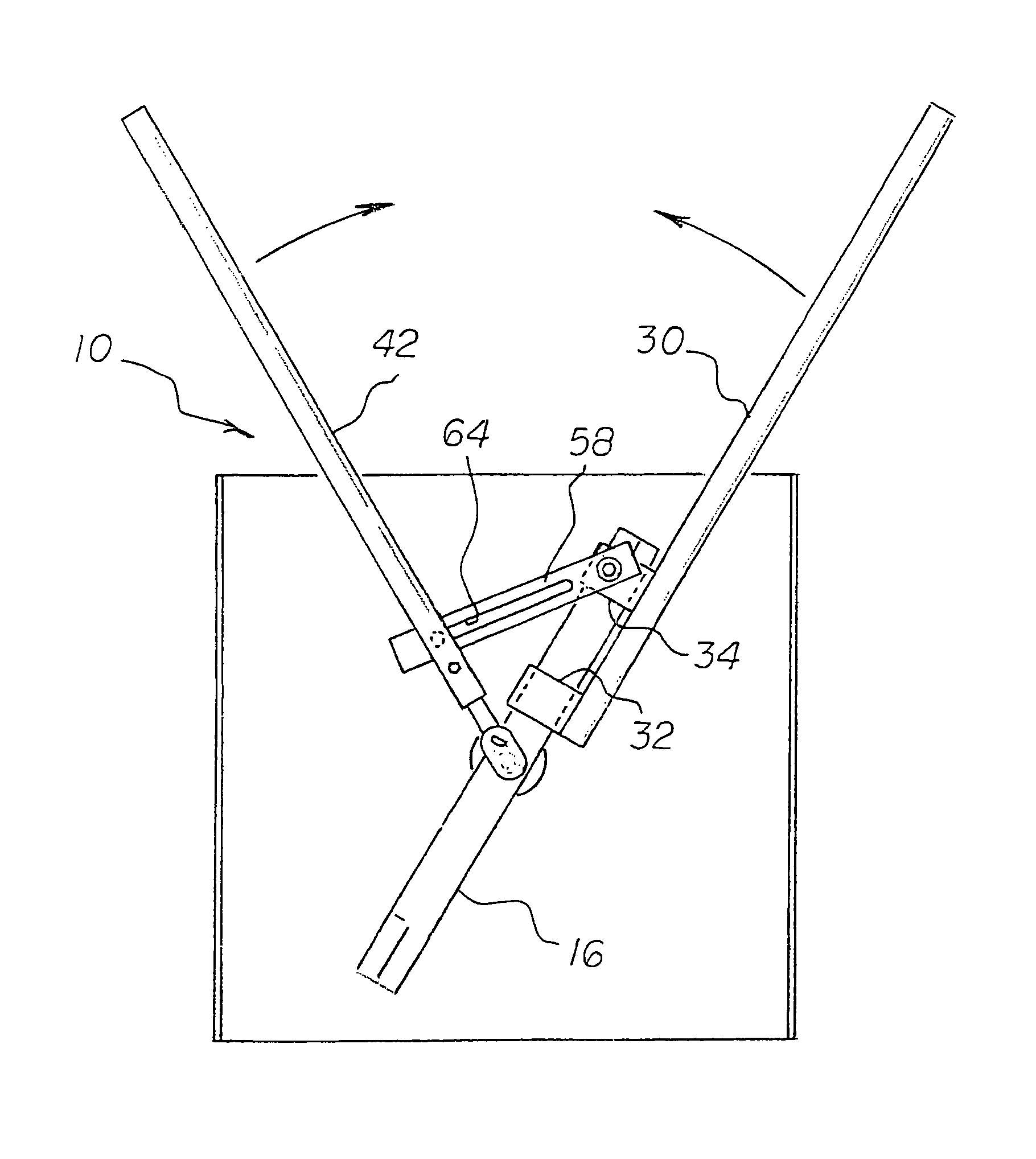
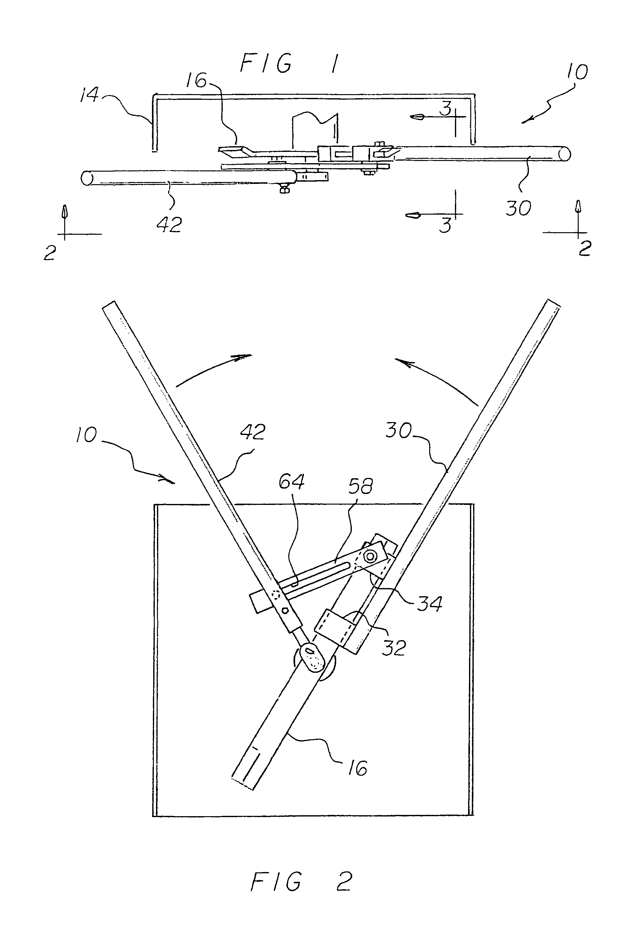
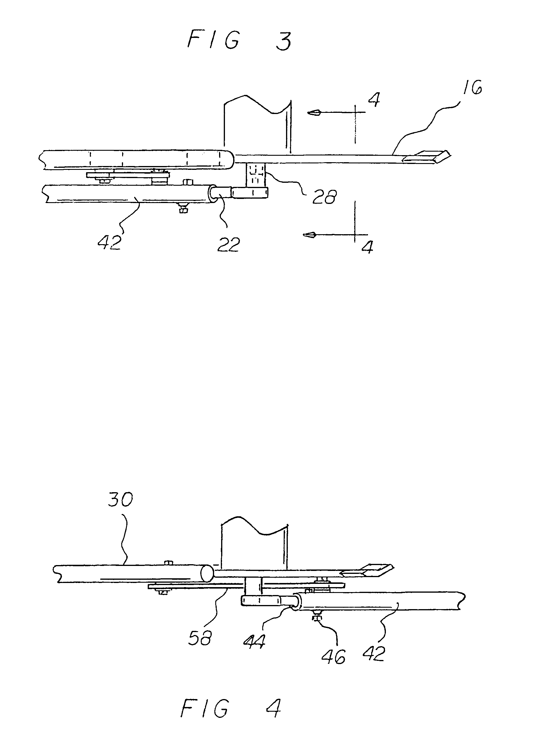
[0033]With reference now to the drawings, and in particular to FIG. 1 thereof, the preferred embodiment of the new and improved blade removal assistance tool system embodying the principles and concepts of the present invention and generally designated by the reference numeral 10 will be described.

[0034]The present invention, the blade removal assistance tool system 10 is comprised of a plurality of components. Such components in their broadest context include a blade pipe, a wrench pipe, and a slide. Such components are individually configured and correlated with respect to each other so as to attain the desired objective.

[0035]The blade removal assistance tool system 10 of the present invention is for removing locking nuts from mowing blade shafts. The removing is done in a safe, convenient and economical manner. First provided is a lawn mower 14 having a blade 16 rotatable in a horizontal plane. A locking nut 18 removably couples the blade to the lawn mower. The blade is rotatabl...


PUM

PropertyMeasurementUnit
heightaaaaaaaaaa
lengthaaaaaaaaaa
lengthaaaaaaaaaa

Abstract

A blade pipe has an exterior end and an interior end with a tube for receiving a lawnmower blade. A locking nut, threadedly received in the tube, retains the blade within the tube. A wrench pipe has an exterior end and an interior end with a recess adapted to receive a wrench. A threaded pivot pin extends radially from the wrench pipe adjacent to the recess. A slide has a blade end and a wrench end, an aperture adjacent to the blade end, and a pivot bolt extending through the aperture and threadedly received in the tube. The slide has a slot slidably receiving the pivot pin.

Description

BACKGROUND OF THE INVENTION[0001]1. Field of the Invention[0002]The present invention relates to a blade removal assistance tool system and more particularly pertains to removing locking nuts from mowing blade shafts, in a safe, convenient and economical manner.[0003]2. Description of the Prior Art[0004]The use of blade removing tools of known designs and configurations is known in the prior art. More specifically, blade removing tools of known designs and configurations previously devised and utilized for the purpose of removing mower blades are known to consist basically of familiar, expected, and obvious structural configurations, notwithstanding the myriad of designs encompassed by the crowded prior art which has been developed for the fulfillment of countless objectives and requirements.[0005]By way of example, U.S. Pat. No. 7,152,326 to Tyler issued Dec. 26, 2006 discloses a Rotary Blade Holding Tool. U.S. Pat. No. 6,796,111 to Williams issued Sep. 28, 2004 discloses a Blade H...

Claims


Application Information

Patent Timeline
Patent Type & Authority Patents(United States)
IPC IPC(8): B25B1/08B25B1/04B25B1/00B25B27/14B23P19/04B25B3/00
CPCA01D34/001A01D34/733B25B23/0085Y10T29/53835Y10T29/53943Y10T29/539Y10T29/53843Y10T29/53896Y10T29/5387
Inventor DEPAZ, DOMINIQUE
Owner DEPAZ DOMINIQUE
Why Eureka
Try Eureka