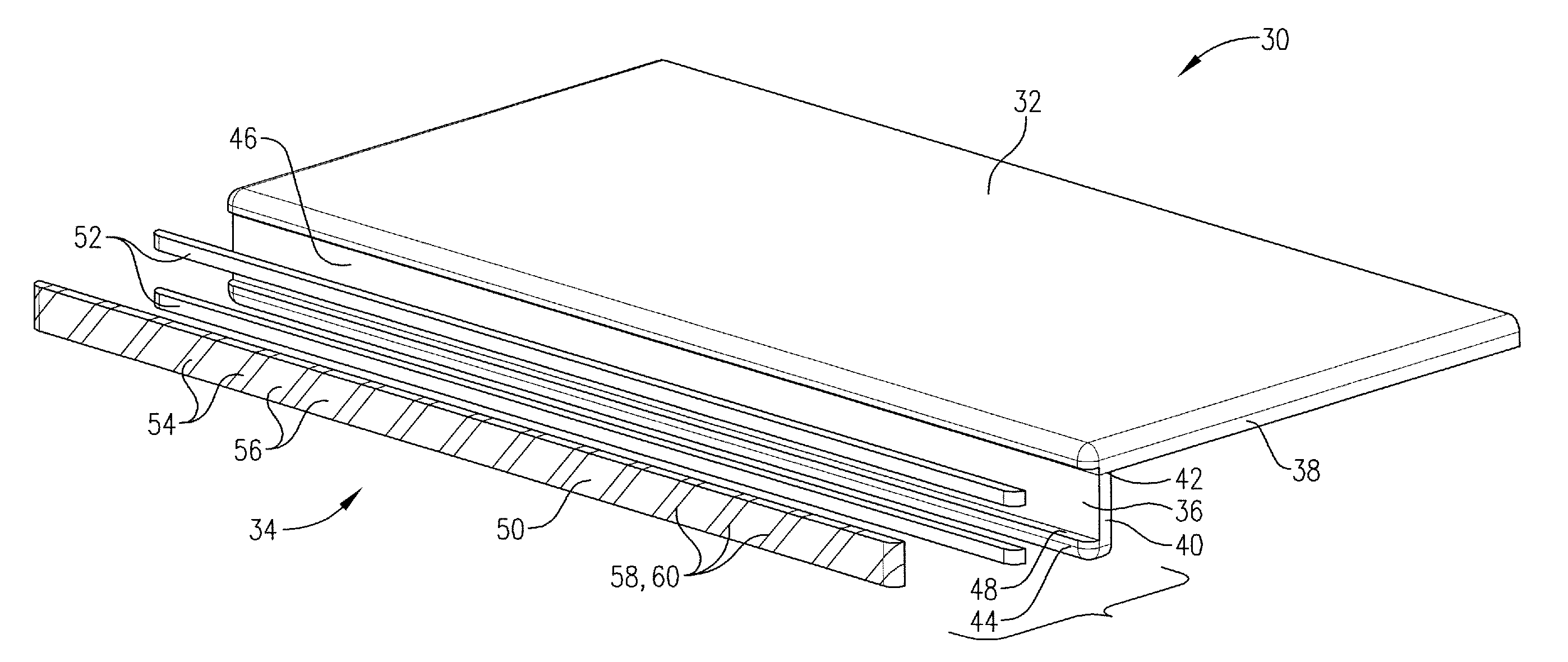
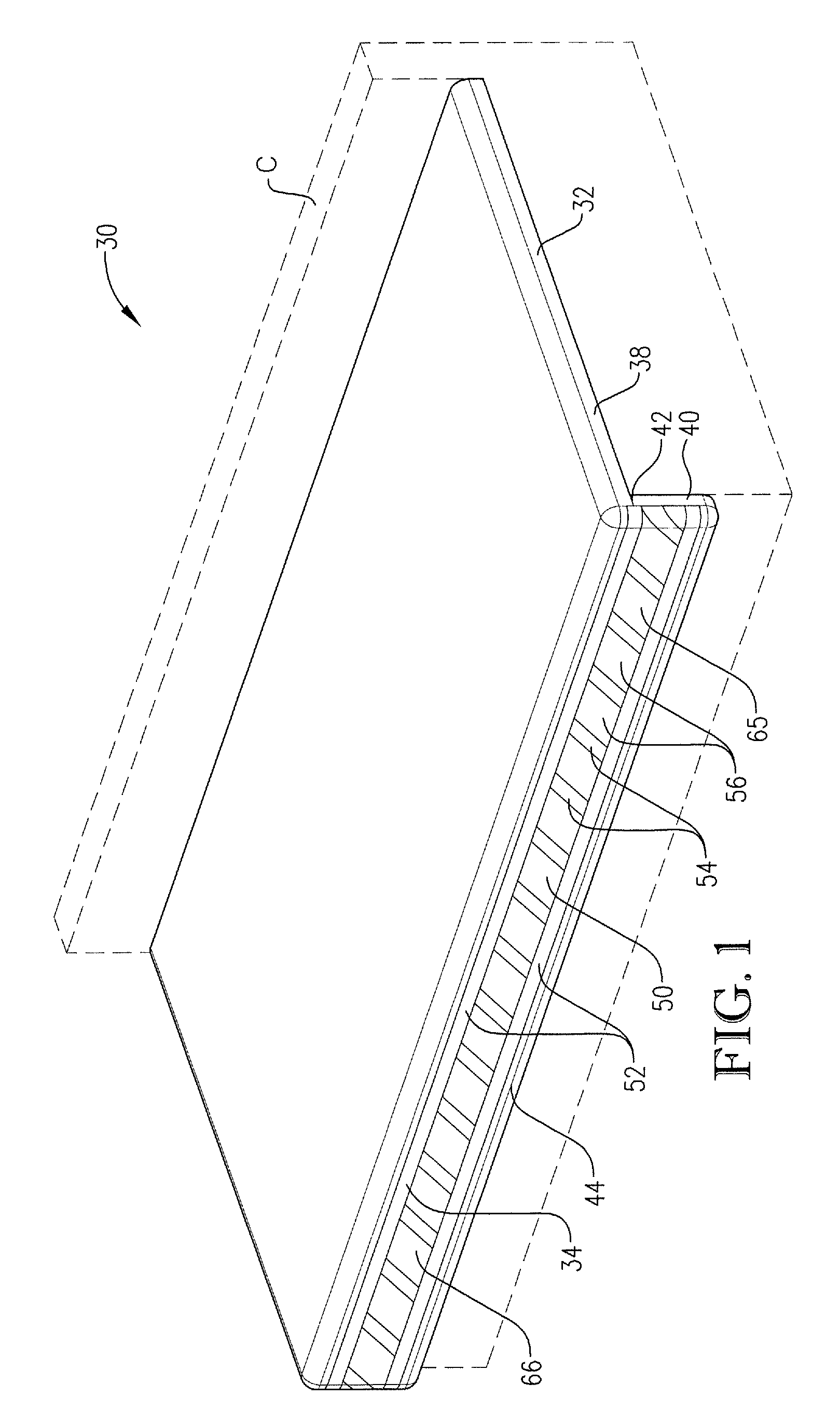
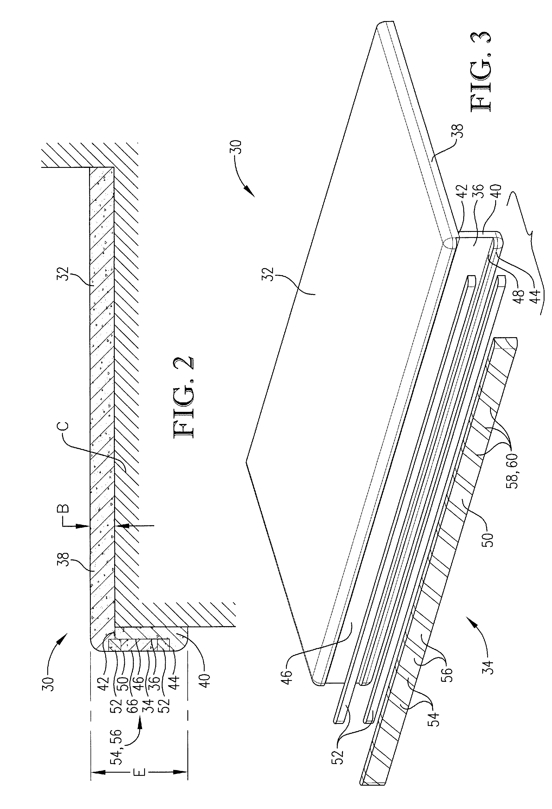
Layered stone trim strip
a technology of layered stone and trim strips, which is applied in the field of manmade stone structures, can solve the problems of prior art stone building products and associated manufacturing methods that are problematic and suffer from various undesirable limitations, deficient prior art methods, and excessive and undesirable stone chipping
- Summary
- Abstract
- Description
- Claims
- Application Information
AI Technical Summary
Problems solved by technology
Method used
Image
Examples
second embodiment
[0053]Turning to FIG. 6, a second inlaid stone composite assembly 100 is constructed in accordance with the present invention and broadly includes a stone body 102 and an alternative stone inlay assembly 104. The body 102 includes laminated sections 106,108 and presents an edge surface 110 and a groove 112. The stone inlay assembly 104 includes a patterned linear inlay assembly 114 and border sections 116. The linear inlay assembly 114 preferably comprises a backed inlay assembly with segments 118,120 adhered to each other and a glass backing 122 adhered to the segments 118,120. It has been found that the illustrated backing 122 provides structural support to the adhered segments 118,120 and serves to maintain the shape of the linear inlay assembly 114 while permitting manufacture of the linear inlay assembly 114 as discussed below. The principles of the present invention are also applicable where the backing 122 comprises a substrate with another material, such as stone, steel, or ...
third embodiment
[0062]Turning to FIGS. 9a and 9b, a third inlaid stone composite assembly 200 is constructed in accordance with the present invention. The illustrated assembly 200 comprises a stone trim strip assembly that can be incorporated into a variety of decorative applications. The assembly 200 broadly includes an alternative stone body 202, an alternative stone inlay assembly 204, and a backing 206. The backing 206 preferably comprises a continuous glass strip, but could comprise a substrate with other materials for providing structural support, such as stone, steel, synthetic resin. Furthermore, the backing 206 could include features for securing the assembly 200 to another object, such as furniture, cabinetry, or an appliance. For example, the backing 206 could include a magnetic material for removably securing the assembly 200 to a metal object (not shown). Alternatively, the backing 206 could include an elongated tray (not shown) with integral fasteners for attaching the assembly to an ...
fourth embodiment
[0066]Turning to FIGS. 10-13, a fourth inlaid stone composite assembly 300 is constructed in accordance with the present invention. The illustrated assembly 300 comprises a backlighted stone countertop panel and broadly includes an alternative stone body 302 and an alternative stone trim assembly 304 similar to assembly 200. The body 302 is mounted on counter C and includes laminated sections 306,308. The body 302 also presents a longitudinal groove 310 defined by a groove base surface 312, side surfaces 314,316, and a shoulder 318 between the side surfaces 314,316, with the body 302 also presenting an edge surface. The groove 310 is formed along the edge surface preferably after the sections 306,308 are laminated, but could also be formed prior to lamination.
[0067]The stone trim assembly 304 broadly includes an alternative stone body 320, an alternative stone inlay assembly 322, and a glass backing 324. The backing 324 preferably comprises a continuous glass strip, but could compri...
PUM
| Property | Measurement | Unit |
|---|---|---|
| thickness | aaaaa | aaaaa |
| thickness | aaaaa | aaaaa |
| thickness | aaaaa | aaaaa |
Abstract
Description
Claims
Application Information
 - R&D
- Intellectual Property
- Life Sciences
- Materials
- Tech Scout
- Unparalleled Data Quality
- Higher Quality Content
- 60% Fewer Hallucinations
Browse by: Latest US Patents, China's latest patents, Technical Efficacy Thesaurus, Application Domain, Technology Topic, Popular Technical Reports.
© 2025 PatSnap. All rights reserved.Legal|Privacy policy|Modern Slavery Act Transparency Statement|Sitemap|About US| Contact US: help@patsnap.com


